Projection lens system and projector

a projection lens and projector technology, applied in the field of projection lens system of projector, can solve the problems of astigmatism, difficult correction of distortion, curvature of field, etc., and achieve the effect of favorable performance and high performan

Inactive Publication Date: 2006-06-06
NITTO OPTICAL CO LTD
View PDF7 Cites 22 Cited by
  • Summary
  • Abstract
  • Description
  • Claims
  • Application Information

AI Technical Summary

Benefits of technology

[0010]In the present invention, a system of retrofocus-type that has negative, positive, and positive refractive powers in this order from the screen side and is suited to enlarging and projecting images is utilized, and two cemented lenses are included in a third lens group. With this arrangement, a low-cost, high-performance lens system in which aberratioris such as distortion are corrected using a low number of aspherical lenses and which is not easily affected by temperature can be provided. That is, a projection lens system according to the present invention projects projected light from a light modulator to a screen, and includes in order from a screen side: a first lens group with a negative refractive power; a second lens group with a positive refractive power; and a third lens group with a positive refractive power. In addition, the third lens group includes at least two cemented lenses and a lens with a positive refractive power positioned on an opposite side of the cemented lenses to the screen.
[0011]A cemented lens, such as cemented doublet lens generates both positive and negative aberrations that cancel out, and makes it easy to correct spherical aberration. Therefore, a cemented lens is suited to correcting spherical aberration which commonly occurs in retrofocus-type lens system. It is possible to improve the correction performance for spherical aberration by increasing the number of cemented lenses. In addition, in the projection lens system, from the point of views of the arrangement of the second and third lens groups, in order from the opposite side to the screen, a lens with the positive refractive power, two cemented lenses (those are the third lens group), and a positive refractive power of the second lens group are arranged and producing a similar construction of the lens combination known as a Gaussian-type. A Gaussian-type lenses arrangement (hereinafter a Gaussian-type) is a symmetric lens arrangement where various aberrations becomes low and it is easy to achieve a favorable balance between different aspects of system performance, making the arrangement suited to lens systems with wide field angles. In addition, since a Gaussian-type can correct various aberrations without using a combination of lenses in which there is a large variation in curvature, the fabrication of parts and assembly are easy even when there is a large number of lenses. A Gaussian-type is also a low-ghost lens arrangement.
[0012]An arrangement of the lens system of the present invention can be explained that the lens system has a Gaussian-type on the input side and a first lens group with a negative refractive power on the output side. In addition, by designing the Gaussian-type combination as a positive second lens group and a positive third lens group, it is possible to provide a projection lens system with high performance that has an overall retrofocus construction and is telecentric on the input side.

Problems solved by technology

However, when a lens system is made wide-angle, it becomes difficult to correct distortion, curvature of field, and astigmatism.
In particular, it is problematic to correct the distortion, curvature of field, and spherical aberration for a retrofocus lens system for a wide-angle lens.
However, there are the problems that aspherical lenses are expensive and are easily affected by minute expansions and / or contractions in the lens surfaces due to changes in temperature.
Additionally, aberration performance is greatly affected by the precision of the lens surfaces during manufacturing.
Accordingly, increasing the number of aspherical lenses makes a lens system costly.
At the same time, when fluctuations in the aberration performance of a plurality of aspherical lenses cannot be cancelled out, such a lens system will be easily affected by temperature changes and / or a performance of such a lens system becomes fluctuate.
In a rear projector such as that shown in FIG. 1, the projection lens system is disposed in a completely closed environment, and compared to a conventional screen and projector system where at least part of the lens system is exposed, such projection lens system is susceptible to the effects of heat.

Method used


Image

  • Projection lens system and projector
  • Projection lens system and projector
  • Projection lens system and projector

Examples


first embodiment

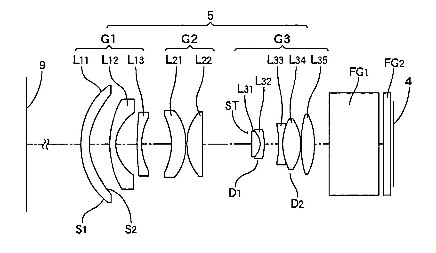
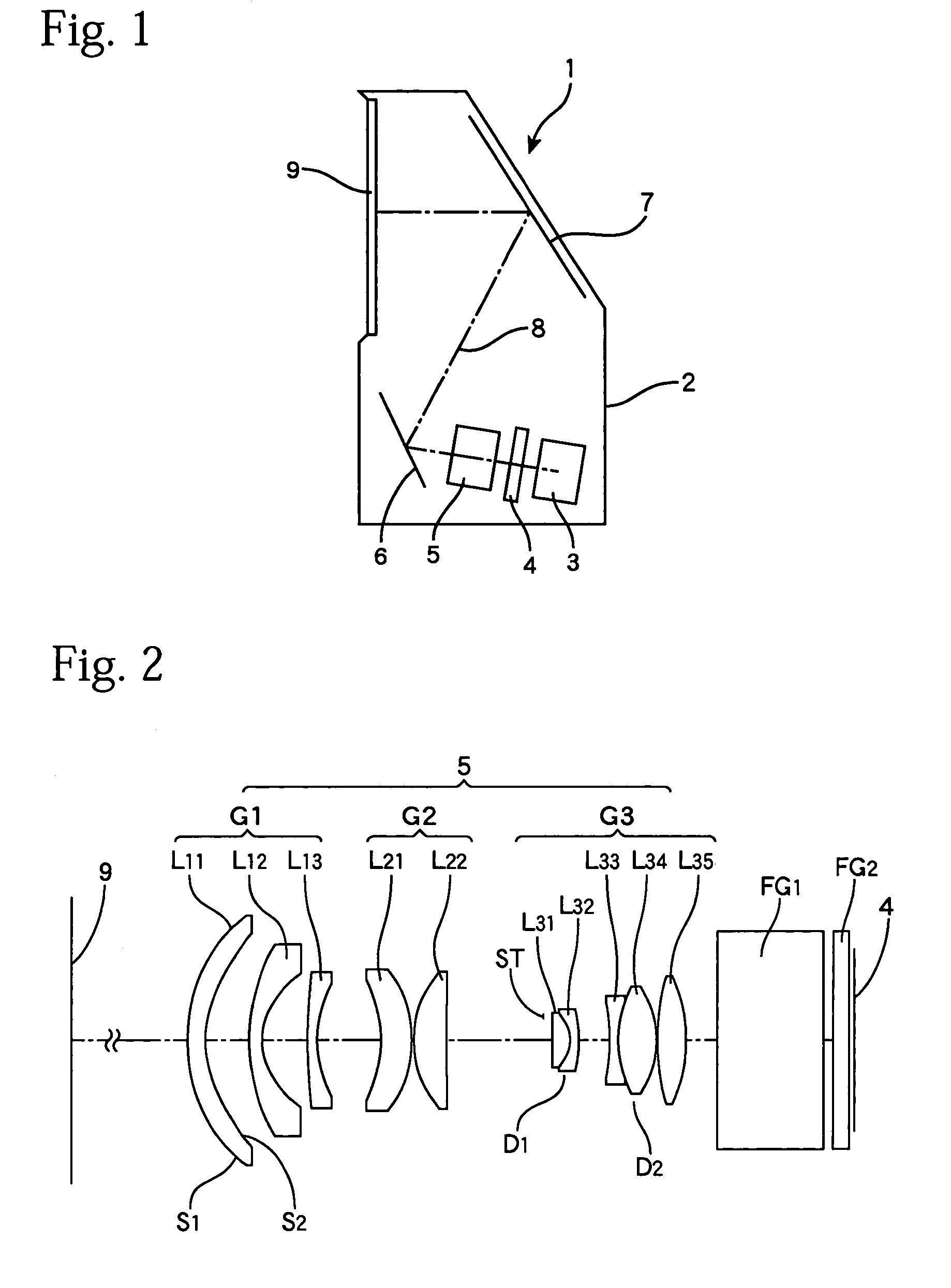
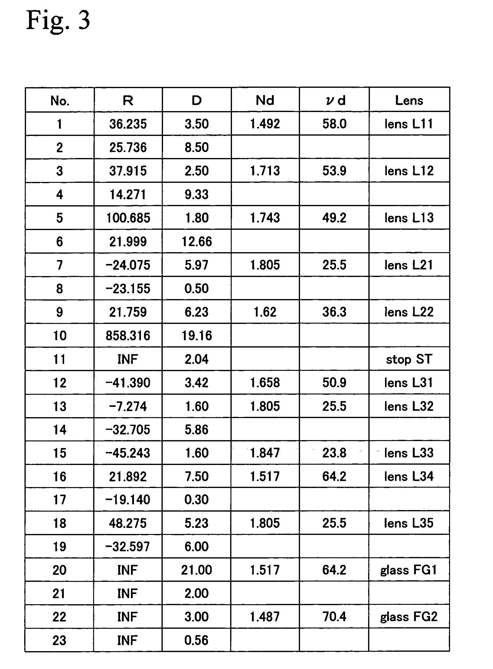
[0036]FIG. 2 shows an arrangement of lenses in a projection lens system 5 according to the present invention. The projection lens system 5 of the present embodiment is constructed of ten lenses that are split into three lens groups G1, G2, and G3 from a screen 9 side (output side) to a light valve 4 side (input side). Parallel glasses FG1 and FG2 disposed between the projection lens system 5 and the light valve 4 are optical low-pass filters.

[0037]The first lens group G1 that is located closest to the screen 9 has an overall negative refractive power and is comprised of three negative meniscus lenses L11, L12, and L13 in order from the screen 9 side, such lenses being convex on the screen side. Both surfaces S1 and S2 of the first lens L11 are aspherical.

[0038]The second lens group G2 has an overall positive refractive power and is comprised of a positive meniscus lens L21 that is concave on the screen side and a convex lens L22 that is convex on the screen side. Also, the third len...

second embodiment

[0065]FIG. 5 shows an arrangement of lenses in a different projection lens system 5 according to the present invention. The projection lens system 5 of the present embodiment includes a first lens group G1 with a positive refractive power and second and third lens groups G2 and G3 with negative refractive powers that are aligned from the screen 9 side towards the input side, with the third lens group G3 including two cemented lenses D1 and D2.

[0066]To describe the lens construction in more detail, the first lens group G1 positioned closest to the screen side has an overall negative refractive power and in order from the screen 9 side has a three-lens construction comprised of negative meniscus lenses L11 and L12 that are convex on the screen side and a negative biconcave lens L13. In the projection lens system 5 of the present embodiment also, both surfaces S1 and S2 of the first lens L11 are aspherical.

[0067]The second lens group G2 has an overall positive refractive power and is c...

third embodiment

[0090]FIG. 8 shows an arrangement of lenses in yet another projection lens system 5 according to the present invention. The projection lens system 5 of the present embodiment also includes a first lens group G1 with a positive refractive power and second and third lens groups G2 and G3 with a negative refractive power that are aligned from the screen 9 side towards the input side, with the third lens group G3 including two cemented lenses D1 and D2.

[0091]To describe the lens construction in more detail, the first lens group G1 positioned closest to the screen side has an overall negative refractive power and has a three-lens construction comprised in order from the screen 9 side of negative meniscus lenses L11 and L12 that are convex on the screen side and a negative bi-concave lens L13. In the projection lens system 5 of the present embodiment also, both surfaces S1 and S2 of the first lens L11 are aspherical.

[0092]The second lens group G2 has an overall positive refractive power a...


PUM


Abstract

A projection lens system that projects projected light from a light modulator to a screen, comprising in order from a screen side: a first lens group with a negative refractive power; a second lens group with a positive refractive power; and a third lens group with a positive refractive power is provided. The third lens group includes at least two cemented lenses and a lens with a positive refractive power positioned on an opposite side of the cemented lenses to the screen. Since the projection lens system achieves a sufficiently high correcting performance for various aberrations using fewer aspherical lenses, it is suitable lens system for a rear projector with high image quality.

Description

BACKGROUND OF THE INVENTION[0001]1. Technical Field[0002]The present invention relates to a projection lens system of a projector that enlarges and projects an image displayed by a light modulator, such as a liquid crystal panel or DMD, onto a screen.[0003]2. Description of the Related Art[0004]Japanese Laid-Open Patent Publication No. 2002-31754 discloses a projection-type image display apparatus that modulates light from a light source in pixel units by transmitting the light using a liquid crystal display device or reflecting the light using a micromirror device (DMD) and then enlarging and projecting the modulated light using a projection lens apparatus so as to produce a visual image.[0005]The projection lens apparatus disclosed by Japanese Laid-Open Patent Publication No. 2002-31754 includes an arrangement of a first lens group with a negative refractive power, a second lens group with a positive refractive power, and a third lens group with a positive refractive power that ar...

Claims


Application Information

Patent Timeline
Patent Type & Authority Patents(United States)
IPC IPC(8): G02B9/12G02B13/04G02B13/18G02B3/00G02B13/16G02B9/00G02B13/24G02B27/18G03B21/00H04N5/74
CPCG03B21/10G02B13/04
Inventor KOBAYASHI, KIWAMU
Owner NITTO OPTICAL CO LTD
Why Eureka
Try Eureka