Head support mechanism, magnetic head assembly, and magnetic disk drive apparatus

a technology of magnetic head and support mechanism, which is applied in the direction of maintaining head carrier alignment, recording information storage, instruments, etc., can solve the problems of crown deformation of slider control method, difficult design and fabrication complicated structure of magnetic head assembly, etc., to prevent the deformation of slider crown, simple structure, and low temperature environment

Active Publication Date: 2008-08-26
TDK CORPARATION
View PDF11 Cites 22 Cited by
  • Summary
  • Abstract
  • Description
  • Claims
  • Application Information

AI Technical Summary

Benefits of technology

[0012]It is therefore an object of the present invention to provide a head support mechanism for supporting a magnetic head slider that includes a thin-film magnetic head, a magnetic head assembly with the head support mechanism, and a magnetic disk drive apparatus with the magnetic head assembly, whereby possible crown deformation of the magnetic head slider under a low temperature environment can be prevented with a simple structure and a low manufacturing cost.
[0014]The heating unit capable of producing heat is formed on the slider mounting section of the suspension. Thus, by energizing this heater unit under a low temperature environment, possible crown deformation of the magnetic head slider caused by the difference in thermal expansion coefficient between the magnetic head slider and the suspension can be effectively prevented. This prevention of crown deformation can be extremely easily achieved by means of a simple structure, that is, forming of the heating unit on the slider mounting section. Because of the simple structure, its design and fabrication become easy resulting a low manufacturing cost.
[0019]The heating unit capable of producing heat is formed on the slider mounting section of the suspension. Thus, by energizing this heater unit under a low temperature environment, possible crown deformation of the magnetic head slider caused by the difference in thermal expansion coefficient between the magnetic head slider and the suspension can be effectively prevented. This prevention of crown deformation can be extremely easily achieved by means of a simple structure, that is, forming of the heating unit on the slider mounting section. Because of the simple structure, its design and fabrication become easy resulting a low manufacturing cost.
[0024]The heating unit capable of producing heat is formed on the slider mounting section of the suspension. Thus, by energizing this heater unit under a low temperature environment, possible crown deformation of the magnetic head slider caused by the difference in thermal expansion coefficient between the magnetic head slider and the suspension can be effectively prevented. This prevention of crown deformation can be extremely easily achieved by means of a simple structure, that is, forming of the heating unit on the slider mounting section. Because of the simple structure, its design and fabrication become easy resulting a low manufacturing cost.

Problems solved by technology

However, according to this known method described in U.S. Pat. No. 6,950,266, the structure of a magnetic head assembly becomes complicate and, due to insertion of the piezoelectric actuator having a significant thickness between the tongue portion and the slider, the design and fabrication of the magnetic head assembly become difficult to increase the manufacturing cost.
Further, the control method of the piezoelectric actuator for compensating the crown deformation of the slider also becomes complicate.

Method used


Image

  • Head support mechanism, magnetic head assembly, and magnetic disk drive apparatus
  • Head support mechanism, magnetic head assembly, and magnetic disk drive apparatus
  • Head support mechanism, magnetic head assembly, and magnetic disk drive apparatus

Examples


Embodiment Construction

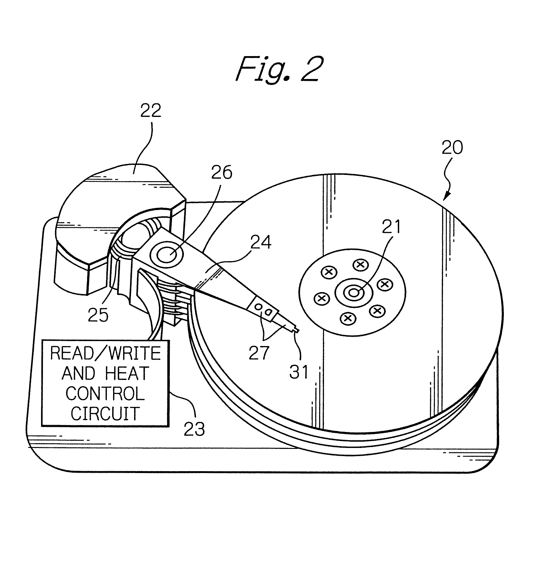
[0052]FIG. 2 schematically illustrates main components of a magnetic disk drive apparatus as a preferred embodiment according to the present invention, FIG. 3 illustrates a configuration example of an HGA shown in FIG. 2, and FIG. 4 illustrates a composite thin-film magnetic head mounted at a top end section of the HGA shown in FIG. 3.

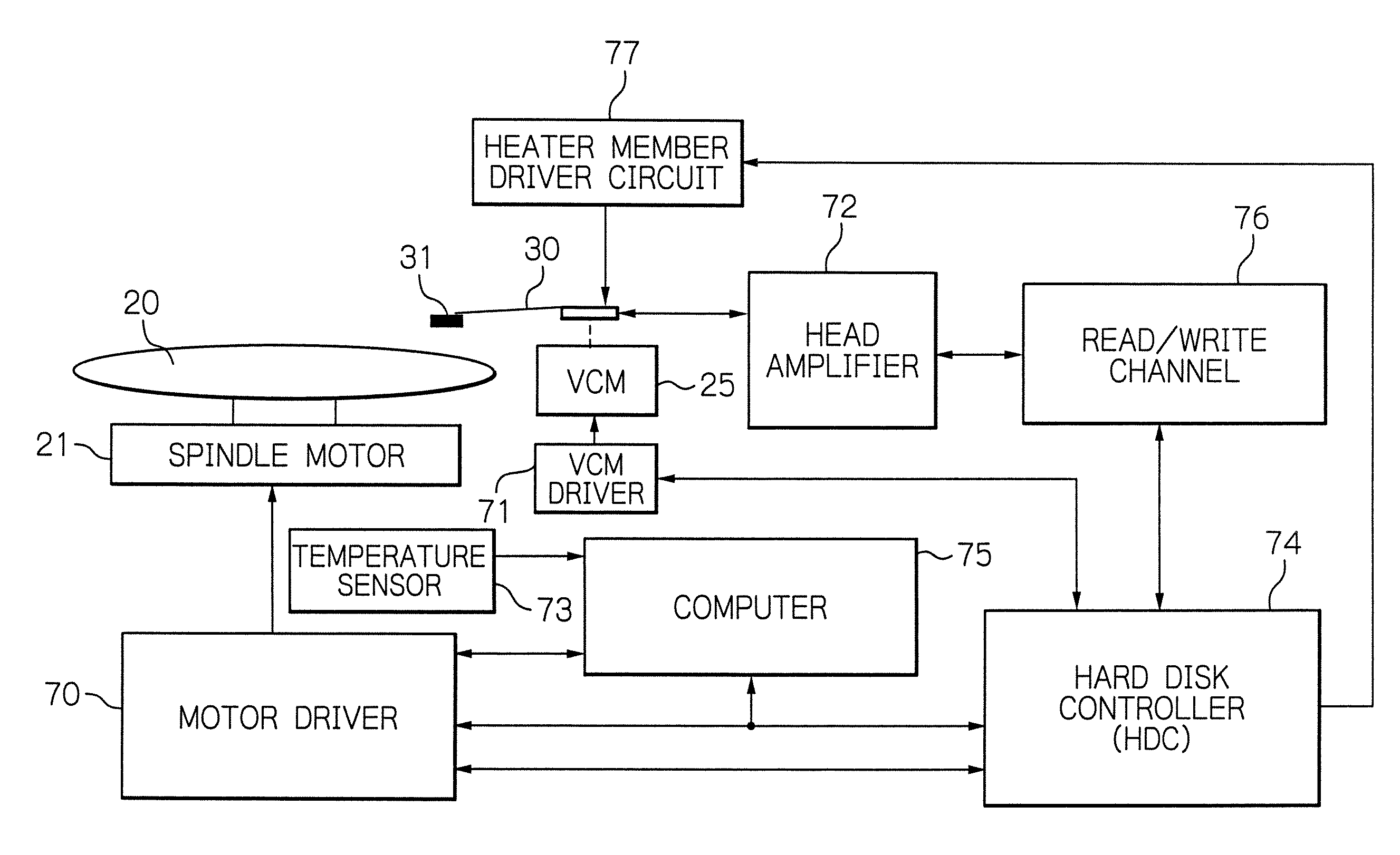
[0053]In FIG. 2, reference numeral 20 denotes a plurality of magnetic hard disks rotating around a rotation axis of a spindle motor 21, 22 denotes an assembly carriage device for positioning each composite thin-film magnetic head or magnetic head slider on a track of each disk, and 23 denotes a read / write and heat control circuit for controlling read and write operations and heating operations of a heater member, respectively.

[0054]The assembly carriage device 22 has a plurality of drive arms 24 stacked along a pivot-bearing axis 26. These drive arms 24 are capable of rotating around the axis 26 and driven by a voice coil motor (VCM) 25. An HGA 27 is m...


PUM

PropertyMeasurementUnit
temperatureaaaaaaaaaa

Abstract

A head support mechanism includes a suspension for supporting a magnetic head slider with a thin-film magnetic head, having a slider mounting section on which the magnetic head slider is fixed, and a heating unit formed on the slider mounting section of the suspension. The heating unit is capable of producing heat.

Description

BACKGROUND OF THE INVENTION[0001]1. Field of the Invention[0002]The present invention relates to a head support mechanism for supporting a magnetic head slider that includes a thin-film magnetic head, to a magnetic head assembly with the head support mechanism, and to a magnetic disk drive apparatus with the magnetic head assembly.[0003]2. Description of the Related Art[0004]In a hard disk drive (HDD) apparatus, thin-film magnetic head elements for writing or recording magnetic information into and / or reading or reproducing magnetic information from magnetic disks are in general formed on magnetic head sliders flying in operation above the rotating magnetic disks. The sliders are supported at top end sections of head support mechanisms configured by suspensions or support arms, respectively.[0005]Recently, such HDD apparatus is assembled not only in a personal computer but also in a mobile equipment such as for example a portable digital audio player, a digital video camera, a mobil...

Claims


Application Information

Patent Timeline
Patent Type & Authority Patents(United States)
IPC IPC(8): G11B5/60G11B21/21
CPCG11B5/6064G11B5/4826
Inventor OTSUKI, MITSUOHIROSE, MASARUKUDO, YOSHIHIROKURIHARA, KATSUKIITO, YUJI
Owner TDK CORPARATION
Why Eureka
Try Eureka