X-ray generating equipment

Inactive Publication Date: 2005-09-22
SHIMADZU CORP
View PDF18 Cites 37 Cited by
  • Summary
  • Abstract
  • Description
  • Claims
  • Application Information

AI Technical Summary

Benefits of technology

[0075] A reflection X-ray generating apparatus, as does a transmission X-ray apparatu

Problems solved by technology

Consequently, the temperature raise evaporates the target material and causes various problems.
This causes a problem that X-rays cannot be generated continuously over a long period of time, or a problem of lowering the operating ratio of the X-ray generating apparatus.
In such a case, the life of the target is short and the X-ray generating apparatus must be halted frequently.
Further, there is a limit to the X-ray intensity that can be outputted.
Since the microfocus X-ray tube is relatively dark, its working throughput cannot be increased.
Thus, X-rays cannot be generated for about two hours, and hence there is a problem of lowering the operating ratio of the apparatus.
In some case the life will be extended by lowering the power, however reducing X-ray intensity and requiring a longer time for fluoroscopy, thereby working throughput will reduce.
Consequently, there is a limit to load power and an upper limit to X-ray intensity, hence working throughput cannot be improved.
Such minute focusing is needed in order to cope with the micro-fabrication of integrated circuits in the semiconductor field today, and therefore is all the more problematic.
Therefore, this reduces the operating ratio of the apparatus.
However, rotational accuracy is insu

Method used


Image

  • X-ray generating equipment
  • X-ray generating equipment
  • X-ray generating equipment

Examples


Example

[0095] Modes for solving the problem of the prior art include the following:

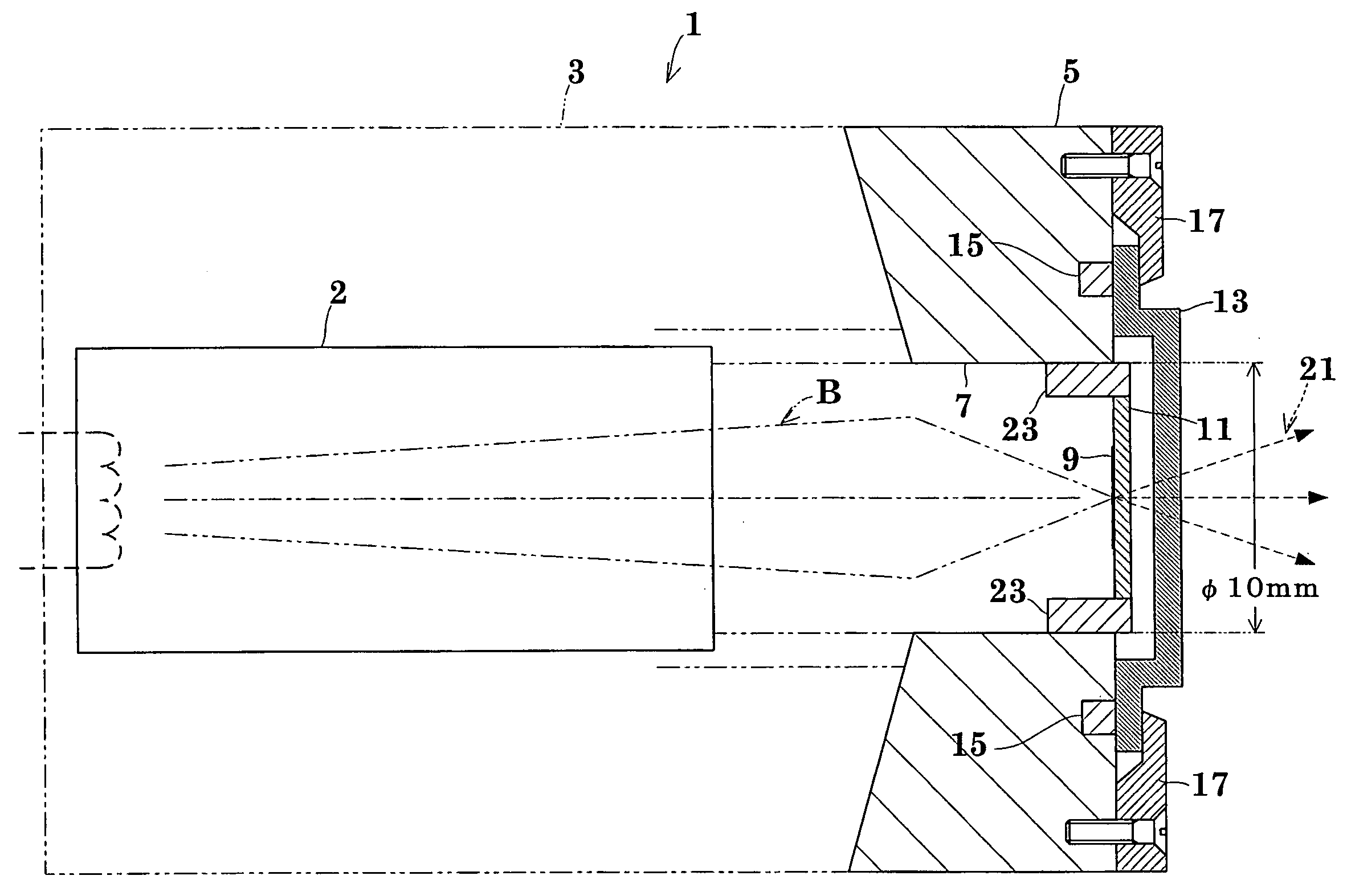
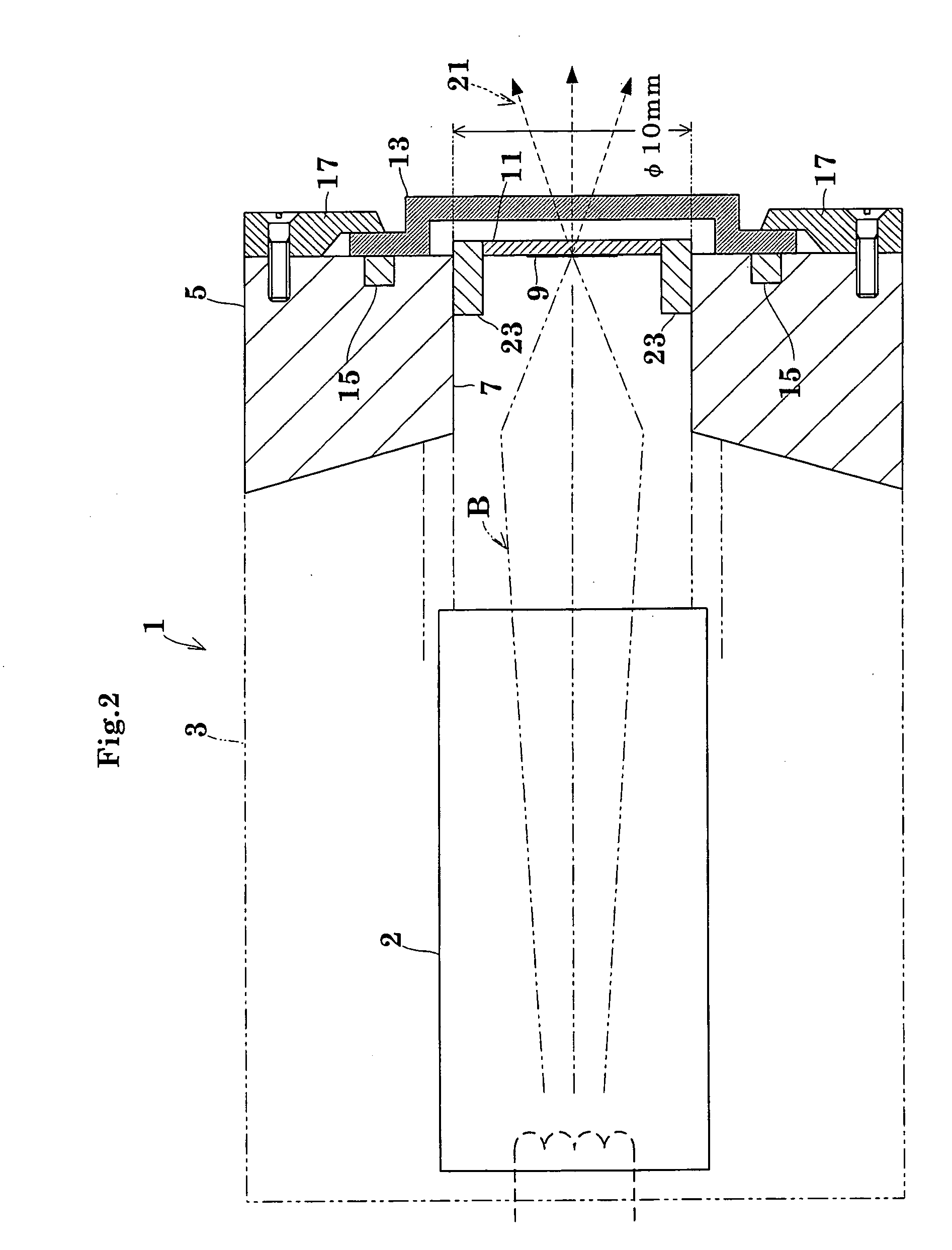
[0096]FIGS. 2 through 5 show one embodiment of this invention. FIG. 2 is a cross section showing a transmission X-ray tube. FIG. 3 is a block diagram showing an outline of an X-ray generating system. FIG. 4 is a schematic drawing showing vibration of an electron beam on a target surface. FIG. 5 is an enlarged schematic drawing showing areas of electron beam collision.

[0097] A transmission X-ray tube 1 has an electron gun 2 mounted in a vacuum vessel 3 for generating an electron beam B. The vacuum vessel 3 has an X-ray generating portion, shown in enlargement, opposed to the electron gun 2. The X-ray generating portion includes an end block 5 that is a part of pole pieces of an electron lens. The end block 5 has the bore 7 that is formed centrally, and the bore 7 is a diameter of 10 mm or less. A target 9 is attached to a holder 11 fitted in the bore 7. The target 9 is made from metal such as tungsten or mo...


PUM


Abstract

An X-ray generating apparatus for generating X-rays by irradiating a target with an electron beam. Wherein the apparatus includes a vibration applying means for vibrating the target in directions parallel to a surface thereof. A colliding spot of the electron beam is movable on the target while maintaining an X-ray focus in the same position on the electron beam without fluctuating the X-ray focal position. This enlarges an actual area of electron collision on the target to disperse the generated heat, thereby to suppress a local temperature rise of the target due to the electron collision. The X-ray generating apparatus is compact, and has a long life and a high X-ray intensity.

Description

TECHNICAL FIELD [0001] This invention relates to an X-ray generating apparatus for a non-destructive X-ray inspecting system or X-ray analyzing system. One of X-ray generating apparatus is a X-ray tube comprising a cathode with an electron-emissive element and an anode with an anode target plate which are accommodated in an vacuum envelope. More particularly, the invention relates to an apparatus having a very small X-ray source sized in the order of microns to obtain fluoroscopic images of a minute object. BACKGROUND ART [0002] X-ray generating apparatus of the type noted above are disclosed in Japanese Unexamined Patent Publications 2002-25484, 2001-273860 and 2000-306533, for example. [0003] In these apparatus, electrons (Sa [A]) are emitted from an electron source maintained at a high negative potential (−Sv [V]) in a vacuum. Secondly, the electrons are accelerated by a potential difference between the electron source and ground potential 0V. Thirdly, accelerated electrons are c...

Claims


Application Information

Patent Timeline
IPC IPC(8): G21K5/02G21K5/08H01J35/08H01J35/28
CPCH01J35/28
Inventor UKITA, MASAAKI
Owner SHIMADZU CORP
Why Eureka
Try Eureka