Bone blocks and methods for inserting bone blocks into intervertebral spaces

a technology of bone blocks and intervertebral space, which is applied in the field of bone blocks, can solve the problems of accelerating the degeneration of vertebrae, affecting the stability of patients' intervertebral space, and affecting the stability of patients, so as to achieve the space for placement, increase the stability of vertebrae, and reduce the effect of nerves

Inactive Publication Date: 2005-09-29
NUVASIVE
View PDF99 Cites 45 Cited by
  • Summary
  • Abstract
  • Description
  • Claims
  • Application Information

AI Technical Summary

Benefits of technology

[0014] An important advantage of the present invention is that it provides a system for implanting bone blocks in a patient's intervertebral space in a minimally invasive surgical procedure. In contrast, current interbody fusion devices are typically implanted during open surgery.
[0015] An advantage of approaching posteriolaterally in a minimally invasive procedure is that the passive elements of spinal stability (anterior and posterior longitudinal ligaments, interspinous ligaments, and facet capsule) are not disturbed and provide stability when stretched by the insertion of the bone block.
[0016] The present invention also provides methods for positioning first and second bone blocks in the patients intervertebral space. Preferably, the first and second bone blocks are disposed with their central longitudinally extending axes at an angle to one another so as to give increased vertebral stability. In this aspect of the invention, each of the bone blocks are preferably introduced through percutaneous cannula which are oriented in opposite posterolateral approaches, being disposed at about 70° to 135°, and most preferably 90°, to one another.
[0017] In various aspects of the invention, the first and second bone blocks may optionally be interlocked together in the patient's intervertebral space. In such aspects of the invention, the first and second bone blocks may be interlocked by a variety of techniques including suturing the blocks together, interlocking a protrusion on the first bone block with an aperture on the second bone block or by interlocking a notch on the first bone block with a groove on the second bone block. In addition, the first and second bone blocks may be fastened together by a fastening pin.
[0018] The present invention also provides a system for introducing a bone block into an intervertebral space comprising a two pronged inserter wherein each prong has an outwardly facing convexly curved camming surface for separating adjacent vertebrae and wherein each prong is disposed on opposite sides of the bone block positioned therebetween. The bone block may preferably have lateral protrusions which extend in a longitudinal direction along the length of the bone block. In this aspect, the lateral protrusions on the bone block preferably mate with longitudinally extending grooves on the inner surfaces of the prongs, thereby preventing unwanted motion of the bone block, but permitting the bone block to be slid axially out of the distal end of the inserter.
[0019] An advantage of the present system is that the bone block inserter protects the bone block during insertion, and distracts the adjacent vertebrae by camming action to gain the needed space for placement of the bone block. By distracting the adjacent vertebral bodies, the present invention also decompresses the nerves that may be causing pain.

Problems solved by technology

Such degeneration can occur as a result of aging or trauma and typically results in pinched or damaged nerves between or proximal to the adjacent vertebrae.
Moreover, such discal degeneration causes shifting of the loading along the patient's spinal column, which in turn further accelerates the vertebral degeneration.
A common problem with the existing intervertebral spinal inserts is that they do not provide stabilization in two perpendicular directions in the plane of the patient's intervertebral space.
Another disadvantage is that, during such major surgery, the actual insertion of the intervertebral insert requires distraction of the adjacent vertebrae to first open a sufficiently large passage for the insertion of the insert therebetween.

Method used


Image

  • Bone blocks and methods for inserting bone blocks into intervertebral spaces
  • Bone blocks and methods for inserting bone blocks into intervertebral spaces
  • Bone blocks and methods for inserting bone blocks into intervertebral spaces

Examples


Embodiment Construction

[0071] The present invention provides a novel system for inserting and positioning one or two bone blocks between adjacent vertebrae.

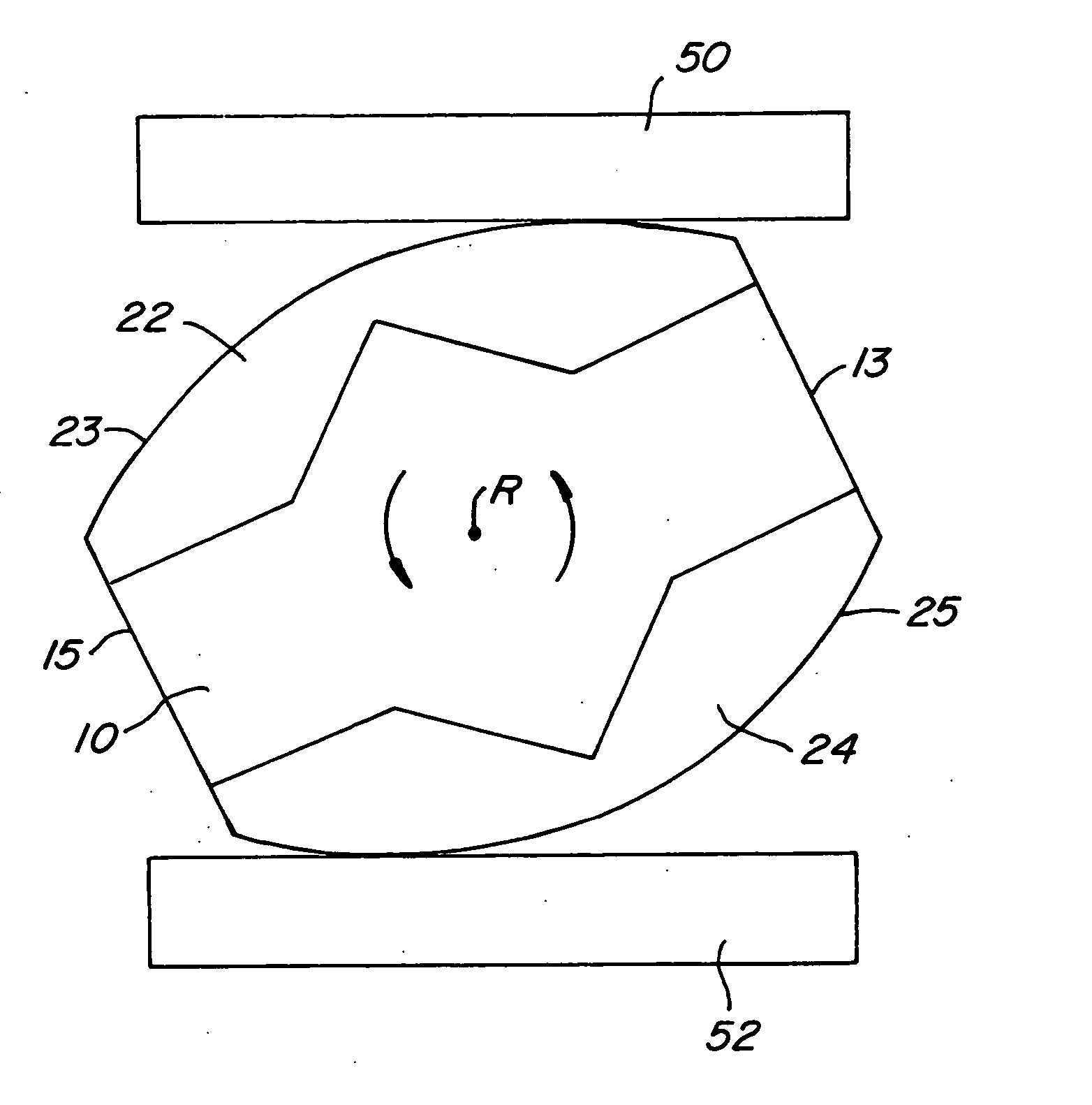
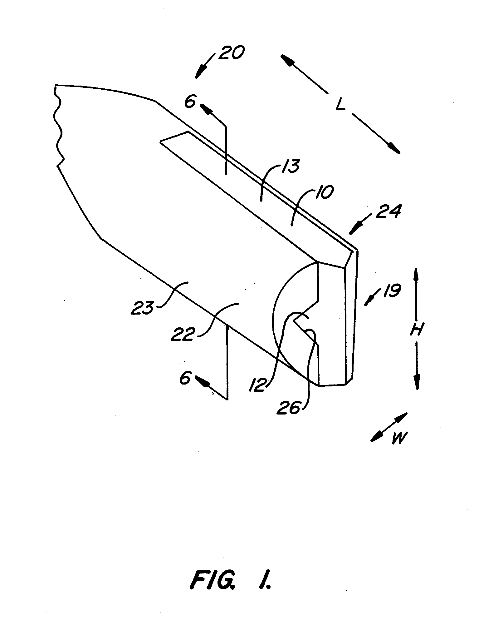
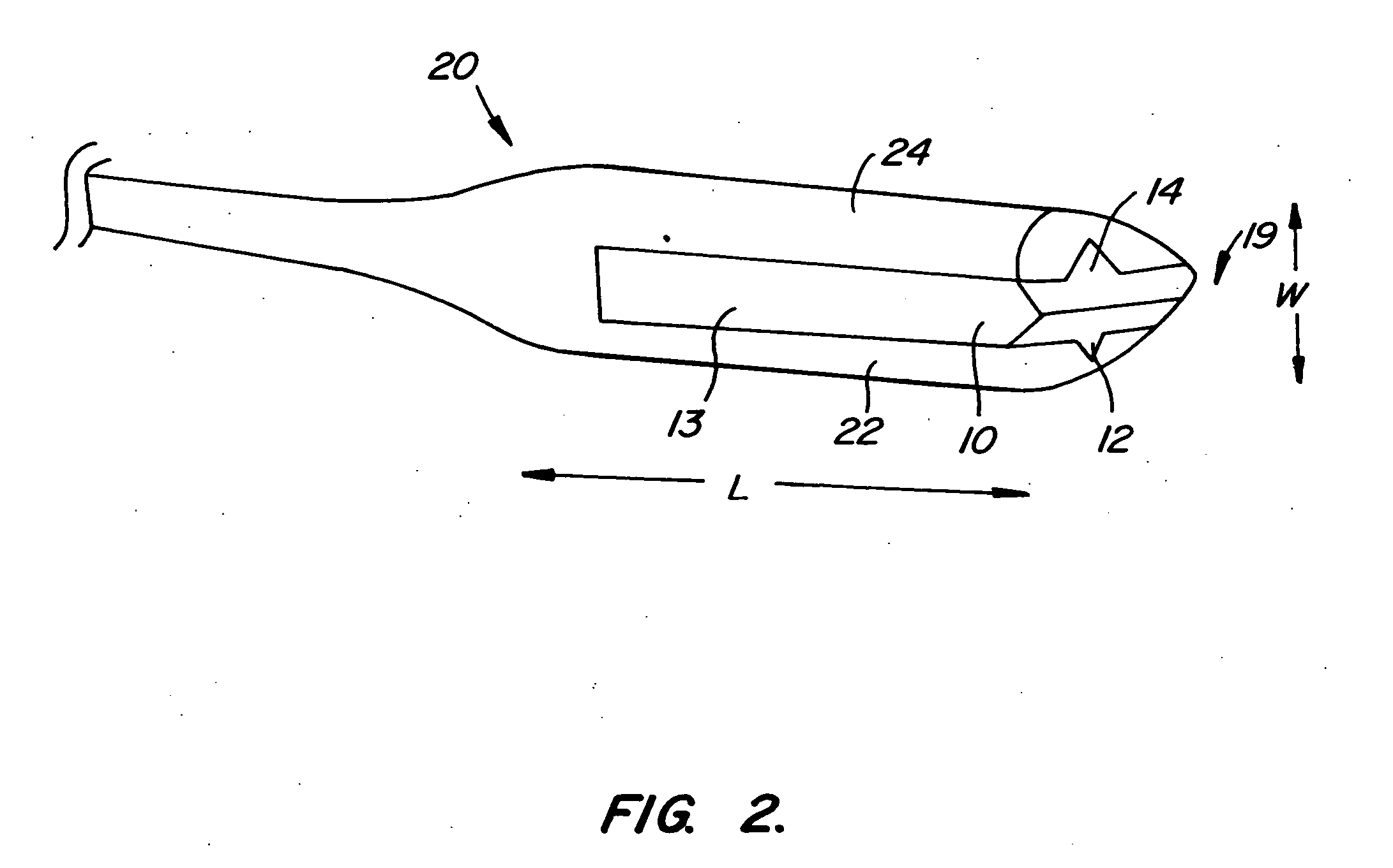
[0072] Referring to FIG. 1, a novel shaped bone block 10 is held between opposite prongs 22 and 24 of bone block inserter 20. Bone block 10 is formed from donor bone tissue, and operates to conduct bone fusion between adjacent vertebrae after it has been implanted between the vertebrae by inserter 20, as will be explained. Prongs 22 and 24 each have curved outer surfaces 23 and 25, respectively, and inner longitudinally extending grooves 26 and 28, (seen more clearly in FIG. 3), respectively.

[0073] Subsequent to placement between adjacent vertebrae, (as will be explained more fully herein), bone block 10 is removed from inserter 20. In a preferred aspect, as shown in FIG. 3, a push rod 30 is preferably received within a longitudinally extending central bore (not shown) in inserter 20. As such, bone block 10 can be held at a fixed position between the...


PUM


Abstract

A bone block for insertion into a patient's intervertebral space. A method for inserting a bone block into a patient's intervertebral space, comprising: supporting the bone block in an inserter; advancing the inserter into the intervertebral space; rotating the inserter, thereby separating adjacent vertebrae; separating the bone block and the inserter with a push rod; and removing the inserter from the intervertebral space.

Description

CROSS-REFERENCES TO RELATED APPLICATIONS [0001] The present application is a division of commonly owned and co-pending U.S. patent application Ser. No. 10 / 032,121, filed on Dec. 21, 2001, which is a divisional application of commonly owned and co-pending U.S. patent application Ser. No. 09 / 320,081, filed on May 26, 1999 and issued as U.S. Pat. No. 6,368,325, the complete disclosure of which is hereby incorporated by reference in its entirety for all purposes. Additionally, the present application claims benefit under 35 U.S.C. § 119(e) from U.S. Provisional Patent Application Ser. No. 60 / 086,945, filed on May 27, 1998; U.S. Provisional Patent Application Ser. No. 60 / 113,651, filed on Dec. 23, 1998; and U.S. Provisional Patent Application Ser. No. 60 / 120,663, filed on Feb. 19, 1999, the entire contents of which are hereby expressly incorporated by reference into this disclosure as if set forth fully herein.TECHNICAL FIELD [0002] The present invention relates to bone block implants wh...

Claims


Application Information

Patent Timeline
Patent Type & Authority Applications(United States)
IPC IPC(8): A61B17/00A61B17/02A61B17/56A61B17/88A61F2/00A61F2/28A61F2/30A61F2/44A61F2/46
CPCA61B2017/0256A61F2310/00359A61F2/4455A61F2/4611A61F2002/30179A61F2002/30331A61F2002/30383A61F2002/30492A61F2002/30604A61F2002/30841A61F2002/4627A61F2220/0025A61F2220/0033A61F2230/0058A61F2/28
Inventor MCKINLEY, JAMES T.MARINO, JAMESSTONE, CORBETT
Owner NUVASIVE
Why Eureka
Try Eureka