Electric device where actuator unit and printed wiring board are connected using bonding parts

Active Publication Date: 2005-10-27
BROTHER KOGYO KK
View PDF9 Cites 17 Cited by
  • Summary
  • Abstract
  • Description
  • Claims
  • Application Information

AI Technical Summary

Benefits of technology

[0009] The present invention has been developed in view of the above-described situations, and it is an object of the invention to provide an electric device in which an actuator unit and a printed wiring board are connected by bonding parts, and which inhibit

Problems solved by technology

This leads to a contact between adjacent two solder bumps each connecting the pad and the auxiliary electrode portion, causing a short-circuit between the individual electrodes.
However, this now deteriorates the strength of the bond between the pad and the auxiliary electrode portion, causing an electrical disconnection due to separation of the pad from the auxiliary electrode portion.
Although it is possible to electrically connect an FPC with a piezoelectric patch without using solder in this wa

Method used


Image

  • Electric device where actuator unit and printed wiring board are connected using bonding parts
  • Electric device where actuator unit and printed wiring board are connected using bonding parts
  • Electric device where actuator unit and printed wiring board are connected using bonding parts

Examples


Embodiment Construction

[0038] Hereinafter, there will be described presently preferred embodiments of the invention, by referring to the accompanying drawings.

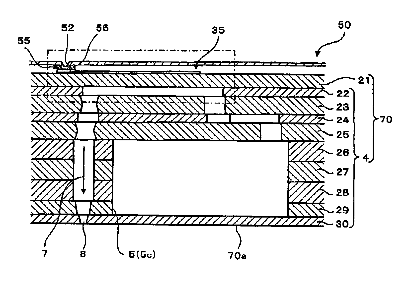
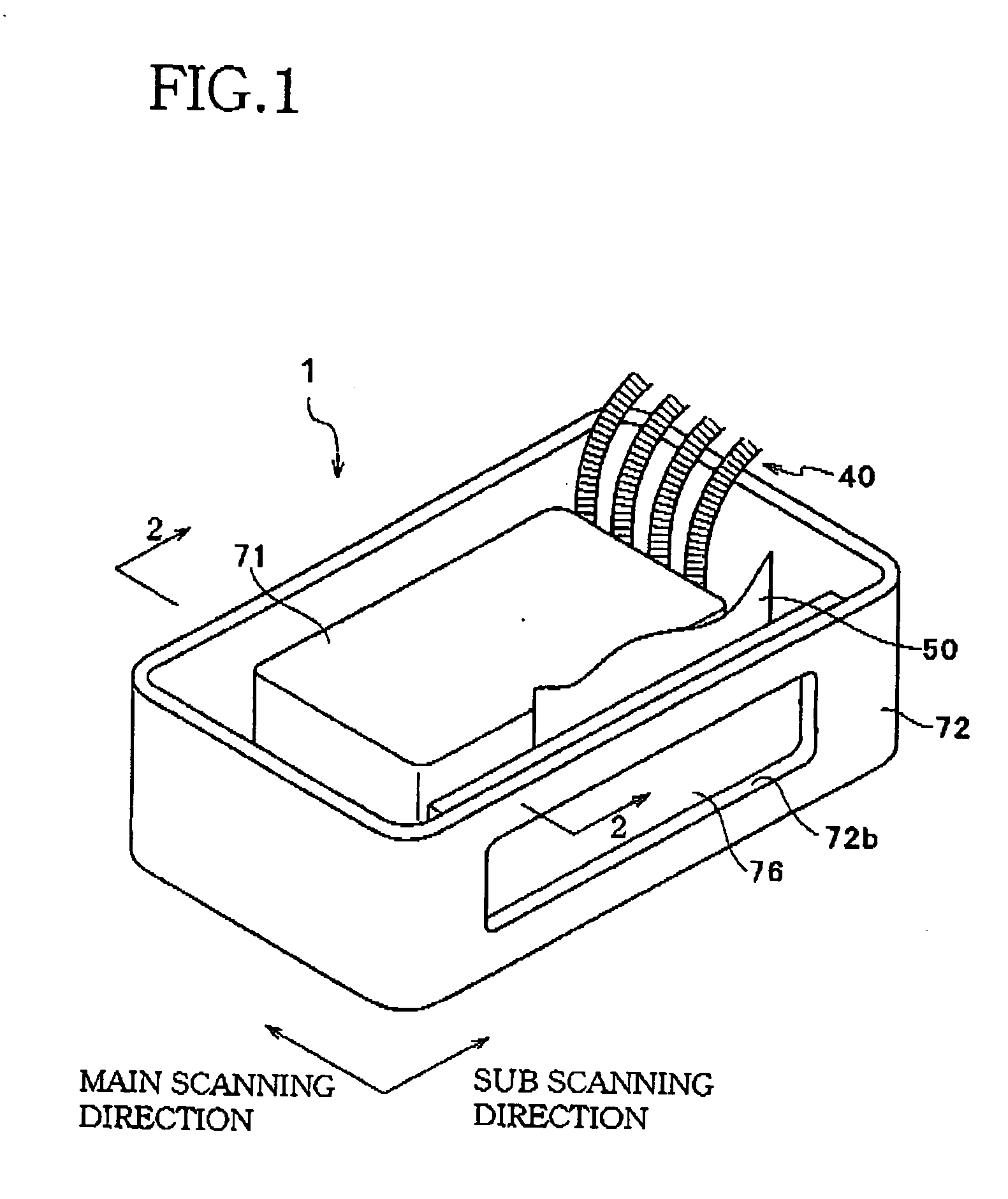
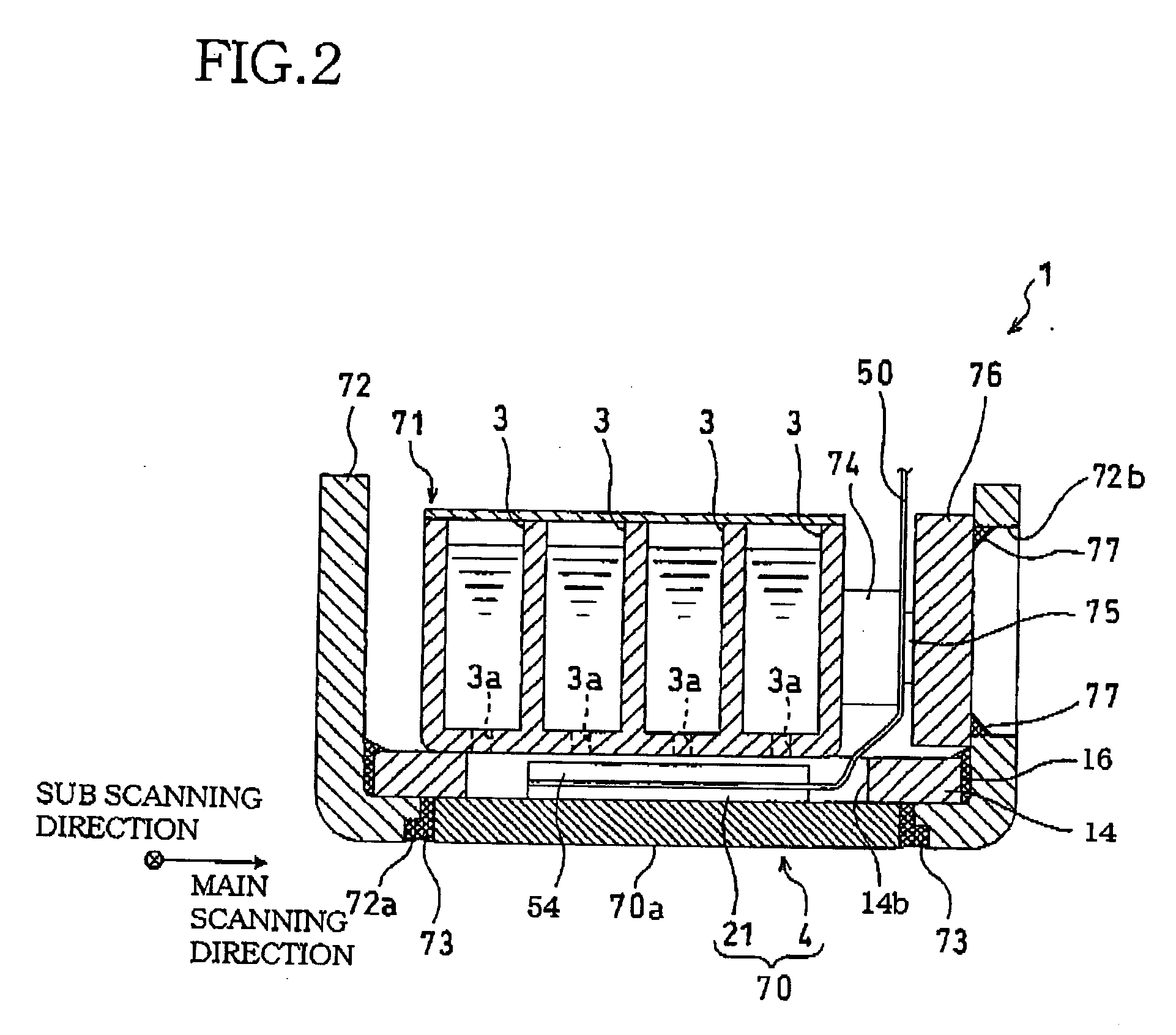
[0039]FIG. 1 is an external perspective view of an inkjet head unit according to a first embodiment of the invention. FIG. 2 is a cross-sectional view taken along a line 2-2 in FIG. 1, showing a state where a printhead is mounted on a holder as a component of the inkjet head unit. FIG. 3 is a perspective view showing a state where a reinforcing plate is bonded to the printhead shown in FIG. 2.

[0040] An inkjet head unit 1 is used in a serial inkjet printer (not shown), and constructed to perform recording by ejecting inks of four colors (cyan, magenta, yellow, and black) onto a recording sheet which is fed in along a sub scanning direction. As shown in FIGS. 1 and 2, the head unit 1 comprises an ink tank 71 in which four compartments 3 for separately storing the four color inks are defined, a printhead 70 disposed below the ink tank 71, and a flexi...


PUM


Abstract

There is disclosed an electric device comprising: an actuator unit which includes a plurality of electrodes formed thereon; a printed wiring board which comprises: an electrically insulating flexible layer which has on one of its opposite sides protrusions for the respective electrodes, each of the protrusions forming a corresponding recess on the other side of the flexible layer; and a plurality of electrically conducting layers disposed on the respective protrusions to be in contact with the respectively corresponding electrodes; and a plurality of bonding parts each of which is in contact with one of the conducting layers and a corresponding one of the electrodes to completely cover a contact portion between the conducting layer and the electrode so as to maintain the contact therebetween.

Description

INCORPORATION BY REFERENCE [0001] The present application is based on Japanese Patent Application No. 2004-130166, filed on Apr. 26, 2004, the content of which is incorporated herein by reference. BACKGROUND OF THE INVENTION [0002] 1. Field of the Invention [0003] The present invention relates to an electric device including an actuator unit for performing printing by ejecting ink droplets onto a recording medium. [0004] 2. Description of Related Art [0005] In an inkjet printhead used in an inkjet printer, as an example of an actuator unit used in an electric device, ink supplied from an ink tank is distributed to a plurality of pressure chambers, and ink droplets are ejected by application of pressure in the form of pulses selectively for the respective pressure chambers. As such an actuator unit, one comprising a laminate of a plurality of piezoelectric sheets of piezoelectric ceramic can be used. [0006] JP-A-2003-311953 discloses an arrangement where a plurality of such actuator ...

Claims


Application Information

Patent Timeline
IPC IPC(8): B41J2/05B41J2/045B41J2/055B41J2/14H05K3/00H05K3/32H05K3/36H05K3/40
CPCB41J2/14209H05K2203/0195B41J2002/14225B41J2002/14306B41J2002/14459B41J2002/14491H05K3/0058H05K3/321H05K3/361H05K3/365H05K3/4007H05K2201/0133H05K2201/0367H05K2201/091H05K2201/10977B41J2002/14217
Inventor HIWADA, SHUHEI
Owner BROTHER KOGYO KK
Why Eureka
Try Eureka