Thermal protector

a technology of thermal protector and thermal shielding plate, which is applied in the direction of protective switch details, tumbler/rocker switches, relays, etc., can solve the problems of difficult stabilization of thermal protector performance, difficult heating of peripheral components, and non-economic numbers

Inactive Publication Date: 2005-12-01
UBUKATA IND CO LTD
View PDF23 Cites 12 Cited by
  • Summary
  • Abstract
  • Description
  • Claims
  • Application Information

AI Technical Summary

Benefits of technology

[0012] In the foregoing construction, the reversing and returning operations of the thermally responsive plate are transferred through the coupler to the heating resistor. Furthermore, the elastic member used for supporting the thermally responsive plate and heating resistor are excluded from the components of the current paths. Accordingly, since the number of components generating heat upon subjection to an overcurrent is reduced other than the heating resistor, the operating current can be set to a large value. In the foregoing construction, particularly, when an electric conductor with a sufficiently small electric resistance is used, an amount of heat generated by the conductor can be restrained to a small value, whereupon the foregoing construction is further effective.

Problems solved by technology

The number of movable and fixed contacts is six in the thermal protector with the three pairs of contacts, which number is non-economical.
That is, there arises a problem that it becomes difficult to stabilize the performance of the thermal protector.
However, since a part which generates heat is limited to the thermally responsive plate, the peripheral components is difficult to heat up.
As a result, the temperature of a motor winding having been increased by the overcurrent cannot be reduced sufficiently during cutoff of current such that a temperature reached by the motor winding is inevitably rendered higher while the thermal protector repeats its reverse and return.
In this case, there is a problem that the increased temperature reduces the insulating performance of an insulating coating of the motor winding thereby to cause a short circuit which leads to possible burn-out.
Further, when a bimetal or trimetal each with a suitable curvature and operating temperature is selected as a material for the thermally responsive plate, the specific resistance of the thermally responsive plate does not always take a suitable value.
That is, there is a problem that it is difficult to design a thermal protector having both suitable values of operating current and operating temperature.
Accordingly, since heat is difficult to be absorbed from the thermally responsive plate to the periphery, it takes more time for the temperature of the thermally responsive plate to decrease.
However, when a protector is arranged which has a large operating current exceeding 200 A, there arises a defect that a large current also flows through components on the current path other than the heating resistor.
When the elastic member is repeatedly heated for a long period of time, the elastic member looses its elasticity, whereupon the contacts cannot be opened.
However, the thickness of the elastic member cannot be increased over the value allowing elastic deformation.
This results in an upper limit of the operating current of the thermal protector, whereby a thermal protector having a large operating current cannot be arranged.

Method used


Image

  • Thermal protector
  • Thermal protector
  • Thermal protector

Examples


Embodiment Construction

[0023] The present invention will be described with reference to the accompanying drawings for more detailed description.

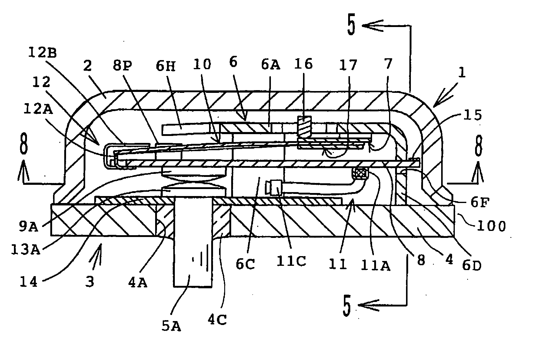
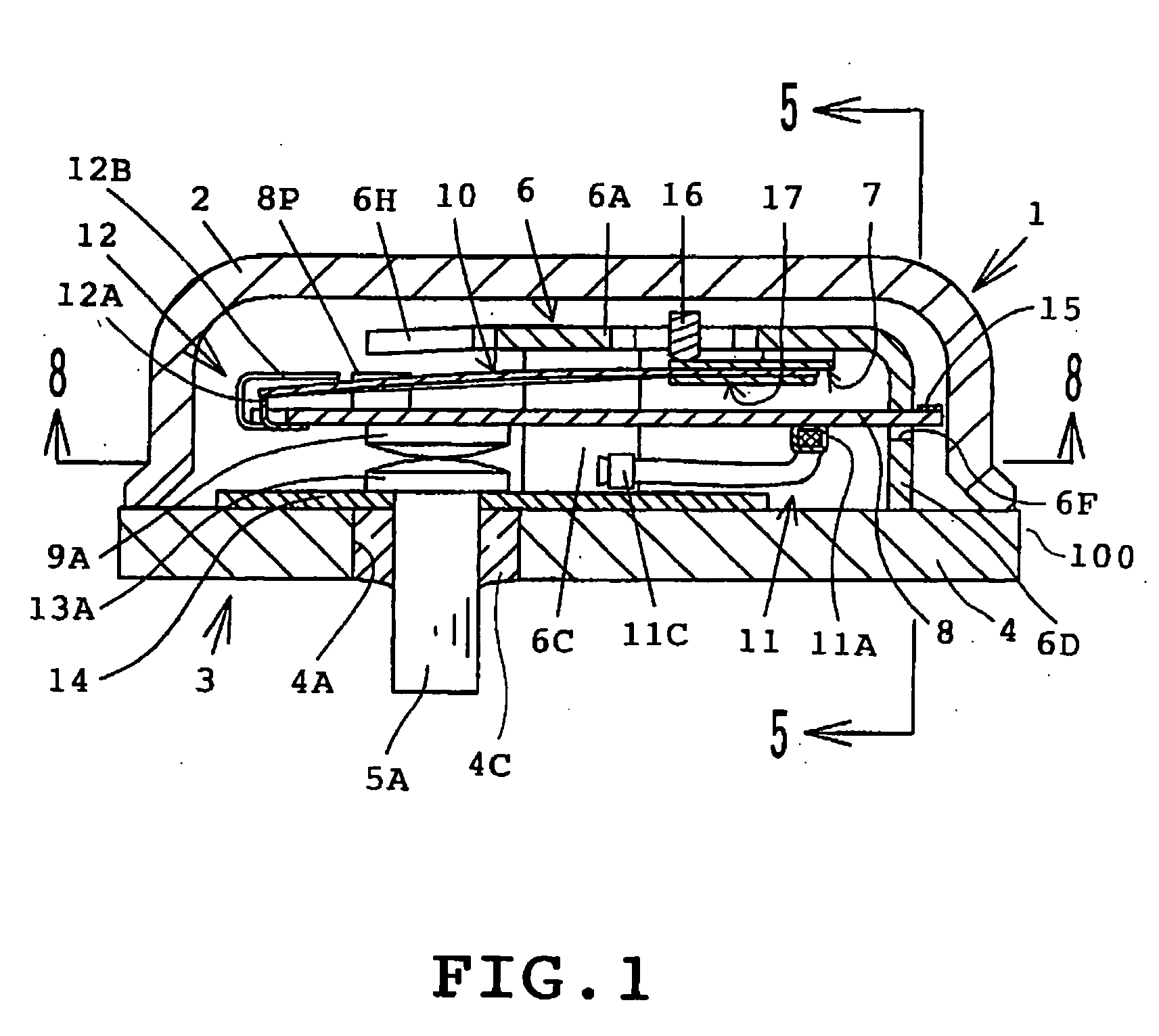
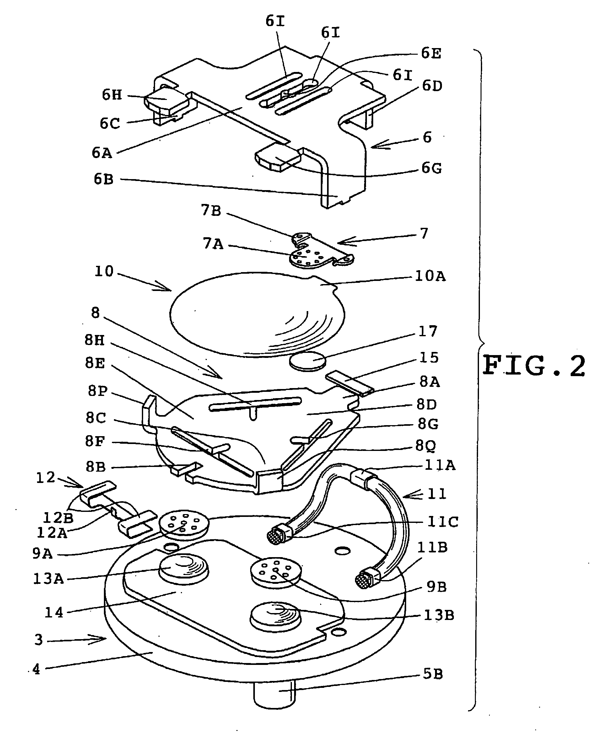
[0024] Firstly, a first embodiment of the invention will be described with reference to FIGS. 1 to 8. FIG. 1 is a longitudinal section of a three-phase internal protector as a thermal protector in accordance with the embodiment of the present invention. FIGS. 2 and 3 are exploded perspective views of the internal protector, showing components of the internal protector. FIG. 4 is a longitudinal section of the internal protector in its operation. FIGS. 5 to 7 are side views of the internal protector with a housing and the heating resistor being eliminated in order that the movement of the heating resistor may be explained. FIG. 8 a cross section taken along line 8-8 in FIG. 1.

[0025] As shown in FIG. 1, the internal protector 1 in accordance with the embodiment has a hermetic container 100 (corresponding to a casing) including a circular dome housing 2 made of a me...


PUM


Abstract

A thermal protector (1) including two fixed contacts (13A, 13B) provided at the end part of conduction terminal pins (5A, 5B) projecting into a metallic enclosed container (100), a support (6) arranged in a case, an oscillatory heating resistor (8) supported by the support and having two movable contacts (9A, 9B) facing the fixed contacts, and a heat responsive body (10) interposed between the heating resistor and the support and coupled with the heating resistor through a coupler (12). When an overcurrent flows through the heating resistor to generate heat therefrom and the temperature of the heat responsive body reaches a set level, the heat responsive body is inverted. Inverting motion of the heat responsive body is transmitted to the heating resistor through the coupler, and the current path is opened.

Description

TECHNICAL FIELD [0001] This invention relates to a thermal protector suitable for protecting, against burnout, electric motors used in enclosed electric compressors, particularly, three-phase motors. BACKGROUND ART [0002] Conventional thermal protectors include a protector having three pairs of contacts as disclosed in JP-B-46-34532 and a protector having two pairs of contacts as disclosed in JP-A-1-105435 and JP-A-10-21808. [0003] The number of movable and fixed contacts is six in the thermal protector with the three pairs of contacts, which number is non-economical. Further, the three movable contacts are secured to a metal plate serving as a heating resistor, and the metal plate is supported in its central portion by a thermally responsive plate. The central portion of the metal plate is pressed such that the three movable contacts are uniformly pressed, whereupon a stable contacting is achieved. However, the metal plate fixed by caulking or the like in a through hole provided in...

Claims


Application Information

Patent Timeline
Patent Type & Authority Applications(United States)
IPC IPC(8): H01H1/20H01H23/00H01H81/02
CPCH01H81/02H01H1/20H01H37/52
Inventor YAMADA, TAKUYA
Owner UBUKATA IND CO LTD
Why Eureka
Try Eureka