Unlock instant, AI-driven research and patent intelligence for your innovation.

Video signal reception apparatus and video signal reception method

a video signal and reception apparatus technology, applied in the field of standardized digital transmission systems, can solve the problems of increasing product prices and complicating structures

Inactive Publication Date: 2006-01-05
KK TOSHIBA
View PDF3 Cites 37 Cited by
  • Summary
  • Abstract
  • Description
  • Claims
  • Application Information

AI Technical Summary

Problems solved by technology

This leads to an increase in a product price and complicates a structure around a cable connection, when independently arranging the connectors complying with the HDMI standard and DVI standard.

Method used


Image

  • Video signal reception apparatus and video signal reception method
  • Video signal reception apparatus and video signal reception method
  • Video signal reception apparatus and video signal reception method

Examples


Embodiment Construction

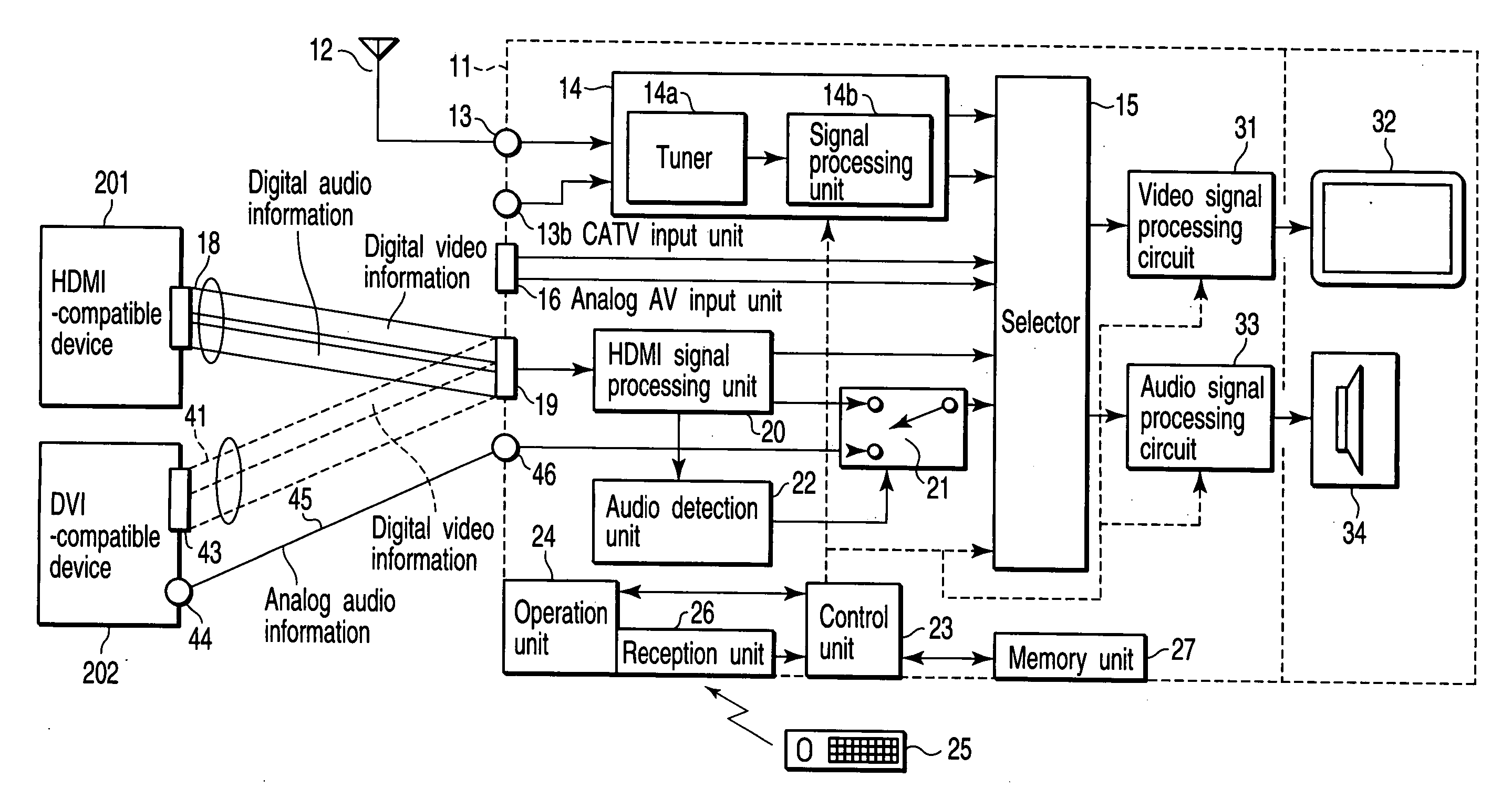
[0016] An embodiment of the present invention will be described in detail below with reference to the accompanying drawing. FIG. 1 is a block diagram showing the example of the schematic arrangement of a video signal reception apparatus 11 in the present invention. This video signal reception apparatus 11 includes functions of receiving a TV (television) broadcast signal, an analog video signal and analog audio signal, and a digital video signal complying with an HDMI standard.

[0017] That is, the TV broadcast signal is received by an antenna 12, and then supplied to a TV signal processing unit 14 via a TV input terminal 13. This TV signal processing unit 14 extracts a predetermined channel signal from the input TV broadcast signal by using a tuner unit 14a, reconstructs the analog video signal and analog audio signal by using a signal processing unit 14b, and then outputs the reconstructed signals to a selector 15. The TV signal processing unit 14 can also receive a signal from, e....


PUM


Abstract

A control unit selects an analog audio signal output from an audio information processing unit, if a digital audio signal received via an HDMI connector is present. If not, the control unit selects an analog audio signal output from an analog audio signal input unit.

Description

CROSS-REFERENCE TO RELATED APPLICATIONS [0001] This application is based upon and claims the benefit of priority from prior Japanese Patent Application No. 2004-193769, filed Jun. 30, 2004, the entire contents of which are incorporated herein by reference. BACKGROUND OF THE INVENTION [0002] 1. Field of the Invention [0003] The present invention relates to a standardized digital transmission system for transmitting a digital video signal obtained by multiplexing digital audio signals and, more particularly, to a video signal reception apparatus and video signal reception method for receiving the digital video signal, and performing specific control for an audio signal system. [0004] 2. Description of the Related Art [0005] As disclosed in Jpn. Pat. Appln. KOKAI Publication No. 9-128182, in recent years, a digital video device which receives and outputs a digital video signal has greatly prevailed. As is known well, a DVI (Digital Visual Interface) standard is widely used as a standar...

Claims


Application Information

Patent Timeline
IPC IPC(8): H03M7/00H04N5/44
CPCH04N5/46H04N5/602H04N5/607H04N21/4882H04N21/43635H04N21/439H04N21/4436H04N21/4341
Inventor MORISHITA, TATSUO
Owner KK TOSHIBA