

System and method for mounting photovoltaic cells
a photovoltaic cell and system technology, applied in photovoltaic supports, climate sustainability, sustainable buildings, etc., can solve the problems of unattractive current pv systems, difficult installation, and current systems tend to be more fragile than desired, so as to maximize energy production and enhance the absorption of available radiation
- Summary
- Abstract
- Description
- Claims
- Application Information
AI Technical Summary
Benefits of technology
Problems solved by technology
Method used
Image

Examples
Embodiment Construction
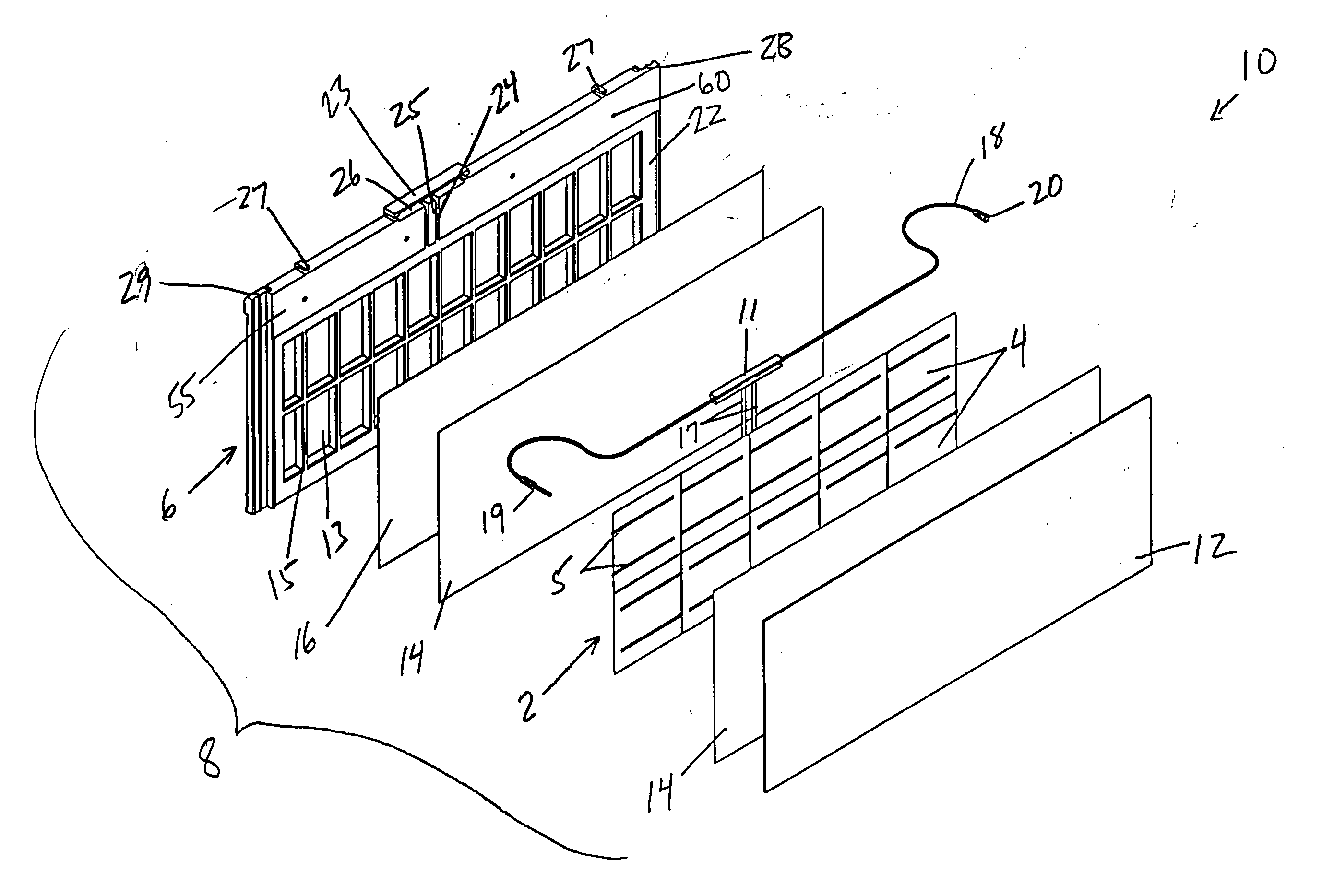
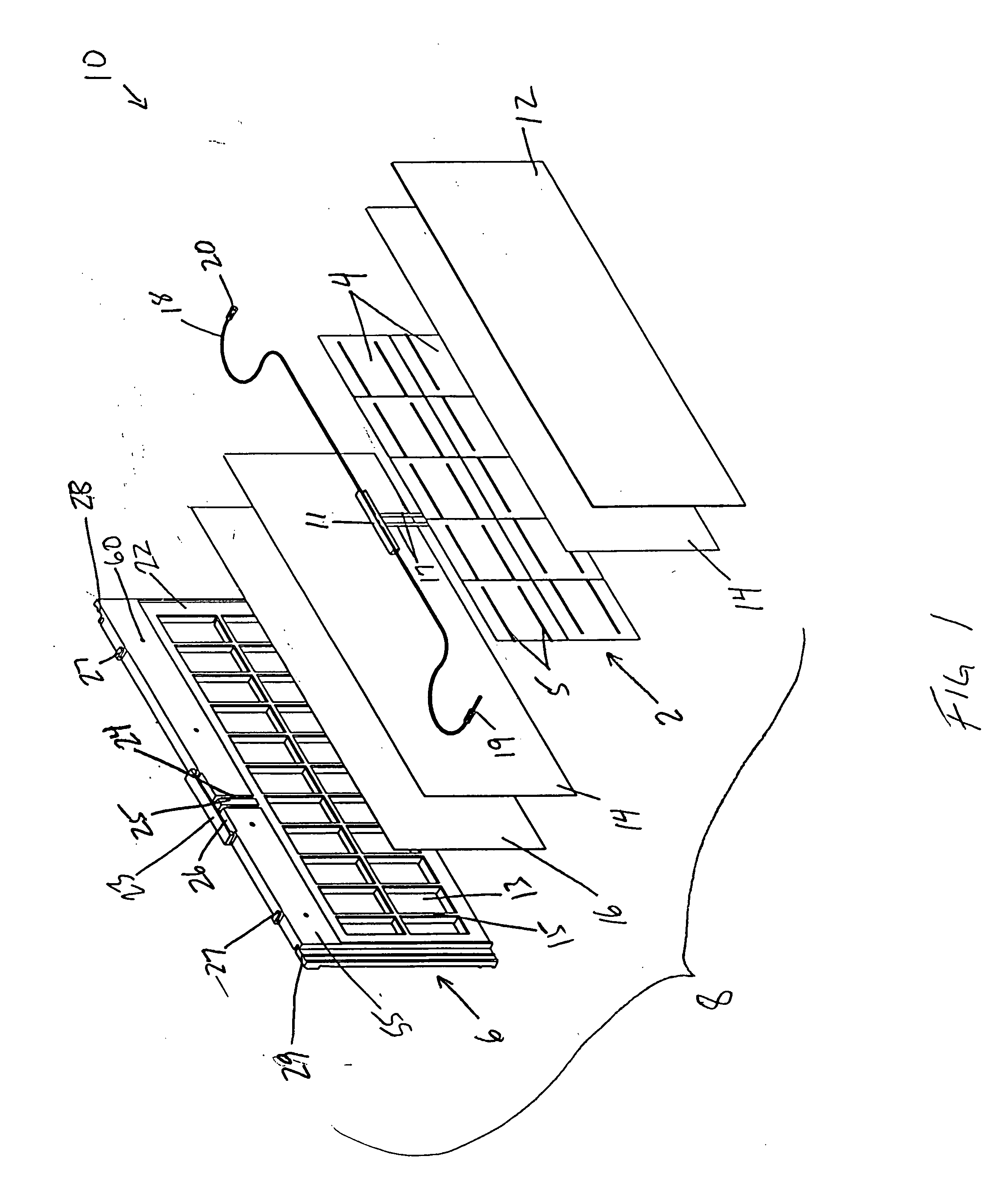
[0026] Considering the drawings, wherein like reference numerals denote like parts throughout the various drawing figures, reference numeral 10 as shown in FIG. 1 is directed to the system according to the present invention.
[0027] In its essence, the system 10 includes a panel 2 of photovoltaic cells 4 mounted in a frame 6.
[0028] Several cells 4, preferably twelve, are electrically connected in series to each other. Ten cells 4 are shown in FIGS. 1 and 2, and combinations of ten, twelve and twenty-four cells 4 are shown in FIGS. 4-6. The panel 2 is the same size in each case; it is the cells 4 that change in size. Each cell 4 has its own set of connection wires 5 to direct current away from the cells 4. The cells 4 are utilized in a panel 2 that is a laminate support structure. Referring to FIG. 1, the support is preferably constructed in layers, with a layer of ethyl-vinyl acetate 14 on either side of and adjacent to the cells 4, a glass outer sheet 12 adjacent the other side of ...
PUM
 Abstract
Description
Claims
Application Information