Power Control system

Active Publication Date: 2006-03-09
WATLOW ELECTRIC MFG
View PDF7 Cites 194 Cited by
  • Summary
  • Abstract
  • Description
  • Claims
  • Application Information

AI Technical Summary

Benefits of technology

[0010] The present invention generally relates to a power control system that includes an integrated operational design. The following presents a summary of the power control system, according to some embodiments of the invention, in order to provide a basic understanding of one or more aspects of the invention. This su

Problems solved by technology

Additionally, such wiring 122 and discrete component installations are often confusing to installers and wiring mistakes often result.
Common mistakes made during installation include incorrect termination of leads to terminals resulting in circuit shorting or opens, poor compression of terminals to leads resulting in potential high temperatures at terminals, electrical magnetic interference with other components, or electromagnetic emissions.
In some applications, this wiring requires the breaking of the power line 304 to introduce the current transformer 302 resulting in another opportunity for wiring mistakes.
Ad

Method used


Image

  • Power Control system
  • Power Control system
  • Power Control system

Examples


Embodiment Construction

[0051] The following description is merely exemplary in nature and is in no way intended to limit the invention, its applications, or uses.

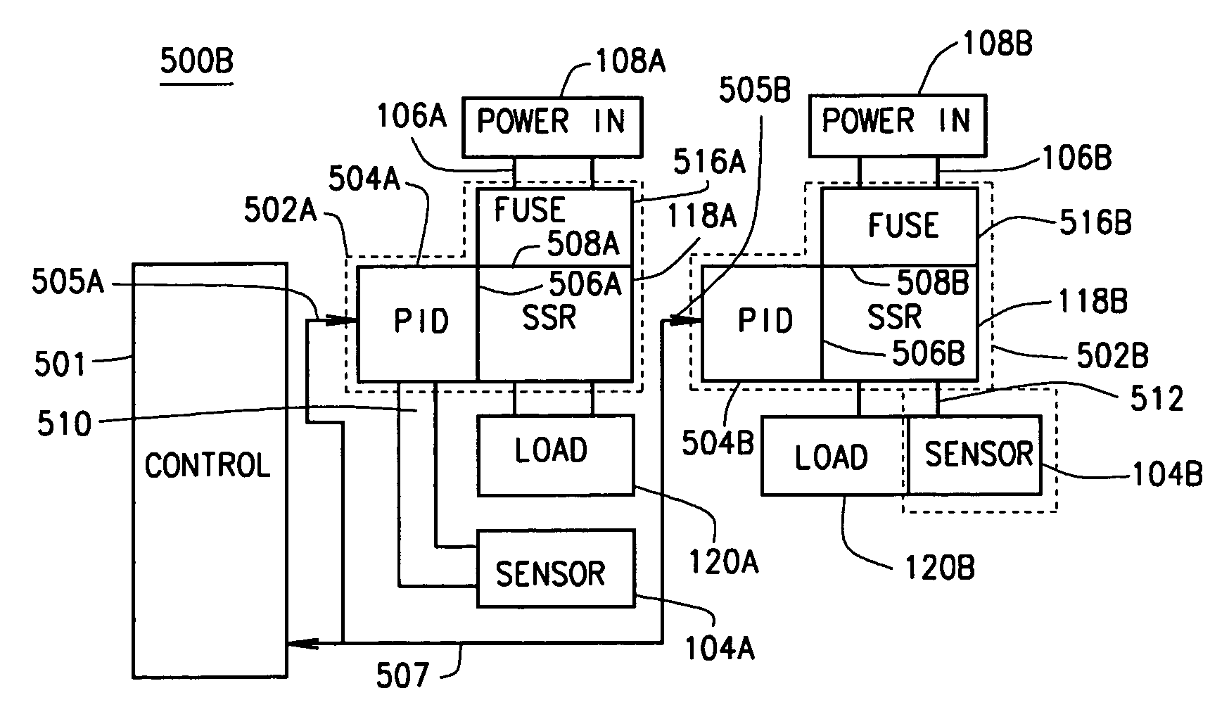
[0052] One embodiment of the invention is a power control system having a power control unit that includes a plurality of power control components. The system includes a unit integration coupling mechanism for mechanical and electrical coupling of a plurality of components into a power control unit. The system also includes a communication link configured to provide a communication among a plurality of power control system components utilizing the coupling mechanism. The system further includes a power switch component adapted for coupling by the unit integration coupling mechanism. The power switch component selectively provides electrical energy to a power load. The power switch includes a power supply interface for receiving power from a power supply, a power load interface for providing, at least a portion, of the received supply power to th...


PUM


Abstract

A power control assembly for use in an integrated power control system has a base with a housing that defines a cavity adapted for receiving a power switch. The control assembly includes a control module configured for generating control signals for controlling the power switch for selectively providing power to a load. A control housing houses the control module and is adapted to be releasably coupled to the base housing and is configured for electrically coupling to control couplers on the base housing for providing the generated control signals to the power switch within the housing cavity upon coupling the control housing to the base housing.

Description

CROSS-REFERENCE TO RELATED APPLICATIONS [0001] This application claims the benefit of U.S. Provisional Application No. 60 / 607,342, filed on Sep. 3, 2004. This application is also related to U.S. patent application No. ______, (Attorney Docket 7377-000121 / US), filed Sep. 2, 2005, entitled INTEGRALLY COUPLED POWER CONTROL SYSTEM HAVING A SOLID STATE RELAY; and PCT patent application No. ______, (Attorney Docket 7377-000121 / WO / POA), filed Sep. 2, 2005, entitled POWER CONTROL SYSTEM. The disclosure of the above applications are incorporated herein by reference.FIELD OF THE INVENTION [0002] The invention relates generally to a control system, and, more particularly, to a control system for controlling power to a power-receiving load. BACKGROUND [0003] A control system for controlling the power provided to a power-receiving load is traditionally produced and deployed on a discrete component basis. Discrete components are selected and combined for the particular application or receiving lo...

Claims


Application Information

Patent Timeline
IPC IPC(8): G05D11/00H02J3/14
CPCH01R9/2425H02J1/14H05K7/1484H05K7/1471H02J13/0006H02J13/0005H02J13/00002H02J13/00036Y02E60/00Y04S10/30H02J3/14G05B11/42
Inventor PFINGSTEN, THOMAS ROBERTCOMMARE, DONALD LEODENNIS, CRAIG RICHARDMCNUTT, LEON J.VON ARX, THEODORE THOMASNESS, KEITH DOUGLASPAPE, ROBERT ALLENLEMKE, JOHN FREDERICTIEDEMANN, LARRY EMILBREITLOW, STANTON HOPKINS
Owner WATLOW ELECTRIC MFG
Why Eureka
Try Eureka