Sheet stacking-aligning apparatus, sheet processing apparatus and image forming apparatus

a technology of stacking and aligning sheets, applied in the direction of electrographic processes, instruments, transportation and packaging, etc., can solve the problems of deteriorating aligning properties, reducing the stacking capacity of sheets, and reducing the cost of the entire apparatus, so as to improve the stacking property. , the effect of increasing the stacking capacity

Inactive Publication Date: 2006-04-13
CANON KK
View PDF23 Cites 4 Cited by
  • Summary
  • Abstract
  • Description
  • Claims
  • Application Information

AI Technical Summary

Benefits of technology

[0011] An object of the present invention is to improve stacking-aligning property for stacked sheet bundle with a simple configuration, and to increase a capacity for the number of stacked sheets while achieving downsizing of the apparatus.
[0014] As explained in the foregoing, the present invention allows to improve the sheet aligning property even in case the stacking tray is made substantially horizontal, whereby a space corresponding to the inclination of the tray can be utilized for a vertical stroke, thus increasing a capacity of the number of sheets stackable on the stacking tray. Also a space saving and a cost reduction can be achieved since a box-shaped stacking tray or a gripper for bundle movement is not employed.
[0015] Also, since the stacking on the stacking trays is achieved with an alignment in the sheet conveying direction by conveying a sheet bundle until a rear end thereof reaches an upper end of a rear end aligning wall thereby causing the rear end to impinge on an upper end of a rear end reference wall, and pressing the rear end of the sheet bundle by the rear end aligning wall, whereby it is rendered possible to avoid positional aberrations of the front end and the rear end of the sheet bundle in the conveying direction and to improve the stacking and aligning of the sheet bundles on the stacking tray.
[0016] Further, since the stacking tray can be positioned with a smaller inclination, it is rendered possible to prevent a buckling phenomenon resulting from a weight of a bundle of sheets.
[0017] Further, in the present invention, as the rear end of a discharged sheet bundle is aligned to the already stacked sheet bundles, at an upstream side in the discharge direction, it is possible to prevent a positional aberration resulting from trapping of the rear end of the discharged sheet bundle by a staple of the already stapled and stacked sheet bundles.

Problems solved by technology

However, in case of stacking sheets of a weak rigidity or showing a downward curl on the stacking tray 400 having a conventional inclined stacking surface as shown in FIG. 10, there may result a buckling of the sheets caused by a weight thereof because of a steep inclination, thereby deteriorating the aligning property.
Also in the sheet processing apparatus as shown in FIG. 12, the gripper 401 is indispensable as the bundle discharge means, and a combination thereof with the box-shaped stacking tray 400 having a horizontal stacking surface renders the entire apparatus bulky and expensive.

Method used


Image

  • Sheet stacking-aligning apparatus, sheet processing apparatus and image forming apparatus
  • Sheet stacking-aligning apparatus, sheet processing apparatus and image forming apparatus
  • Sheet stacking-aligning apparatus, sheet processing apparatus and image forming apparatus

Examples


first embodiment

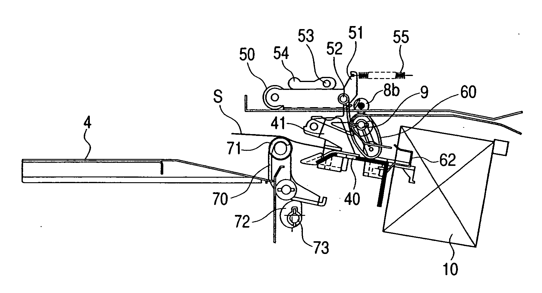
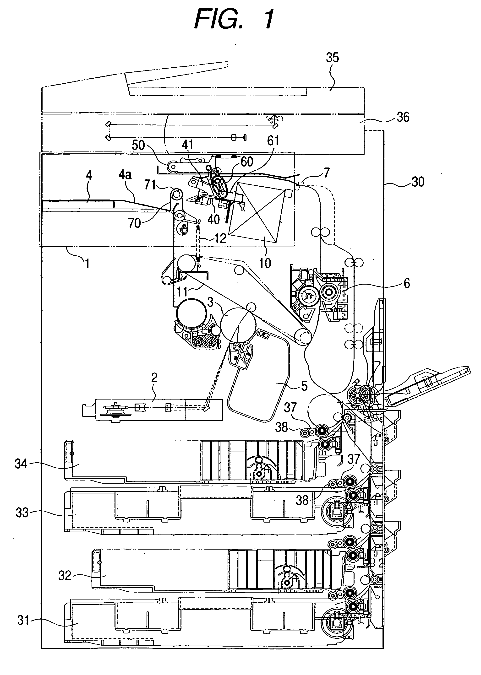
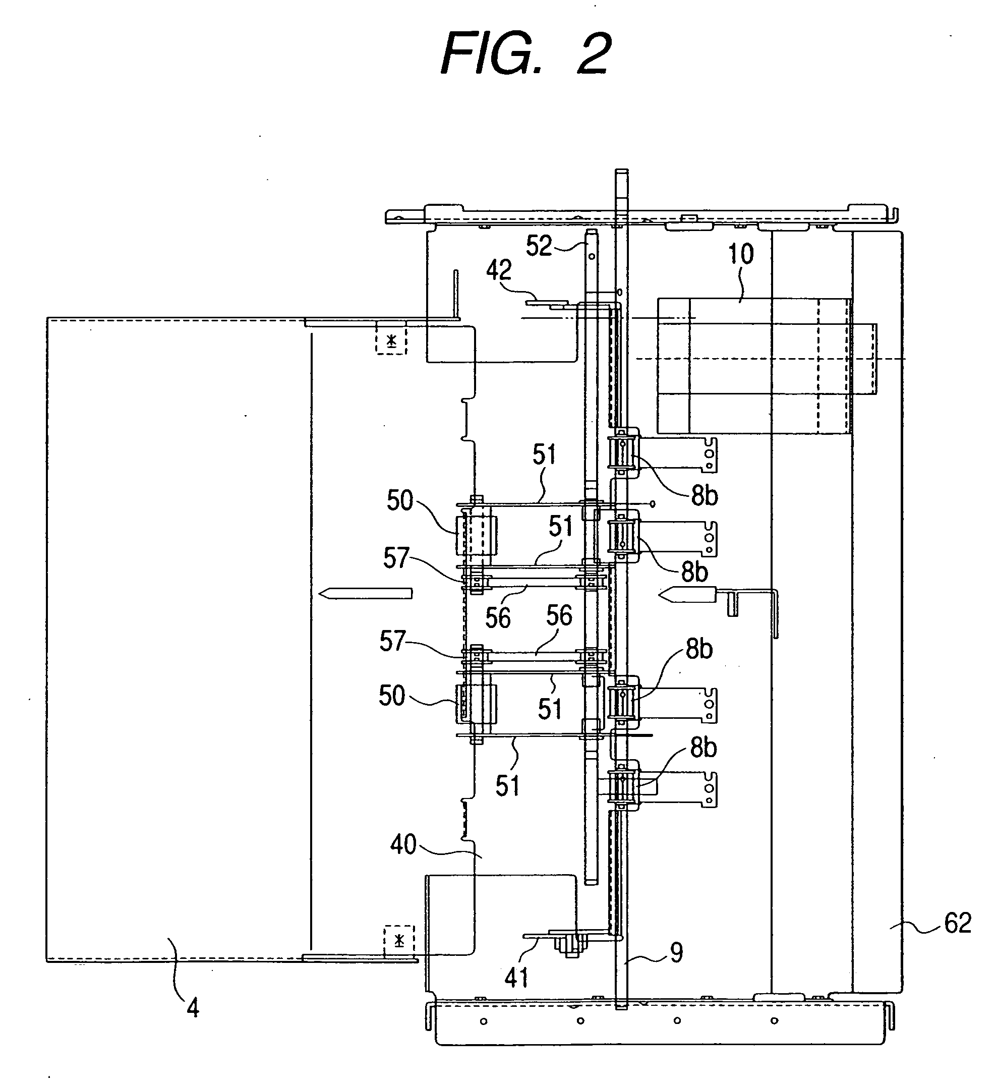
[0033] In the following, there will be given a detailed explanation on an embodiment of the image forming apparatus of the present invention, with reference to the accompanying drawings. FIG. 1 is a cross-sectional view of a main body 30 of an image forming apparatus equipped with a sheet processing apparatus 1 constituting a first embodiment of the present invention, FIG. 2 is a plan view of the sheet processing apparatus 1, and FIG. 3 is a cross-sectional view of the sheet processing apparatus 1.

[0034] Following description will be given on an example of the sheet processing apparatus 1, which is provided on the main body 30 of the image forming apparatus and under an original reading apparatus 35 as shown in FIG. 1, and which temporarily stacks sheets S, discharged after image formation from the main body 30 of the image forming apparatus, on a process tray 40, and, after post processes such as alignment and stapling, stacks and aligns thus processed sheets S on a substantially ...

second embodiment

[0065] In the following there will be explained a second embodiment of the image forming apparatus 3 of the present invention, wherein components equivalent to those in the foregoing first embodiment are represented by same numbers and will not be explained further.

[0066] In the following there will be given an explanation, with reference to FIGS. 8A, 8B and 8C, on means for discharging the sheet bundle S by a parallel displacement of the rear end aligning wall 70 in the sheet conveying direction. As shown in FIGS. 8A, 8B and 8C, the rear end aligning wall 70 is provided with a rack gear 78 formed in the sheet conveying direction integrally with the rear end aligning wall 70, and exerts a parallel displacement in the sheet conveying direction by a driving force transmitted from the rear end aligning wall drive motor 76 through a pinion gear 74 to the rack gear 78 which is supported on the other side by a rack supporting roller 77. Also as shown in FIG. 9, a home position sensor 75 ...


PUM


Abstract

The sheet stacking-aligning apparatus or the sheet processing apparatus includes a substantially horizontal stacking tray, a rear end aligning unit for aligning a rear end of a sheet bundle on the stacking tray, and a control unit for controlling an operation of the rear end aligning unit for aligning the sheet bundle when it is in an upstream position of the stacking tray, and the stacking tray is provided substantially horizontally. It is thus made possible to increase the stacking space, thereby increasing the number of stackable sheets and to achieve the alignment of the rear end of the sheet bundle with a simple configuration, thereby improving the stacking-aligning property of the sheet bundle on the stacking tray.

Description

BACKGROUND OF THE INVENTION [0001] 1. Field of the Invention [0002] The present invention relates to a sheet stacking-aligning apparatus for aligning and stacking sheets, a sheet processing apparatus provided with such sheet stacking-aligning apparatus, and an image forming apparatus provided with such sheet processing apparatus. In particular, the present invention provides a sheet stacking-aligning apparatus with an improved stacking-aligning ability for a sheet bundle and capable of achieving space saving, a cost reduction and an increase in the capacity of the number of stacked sheets, a sheet processing apparatus provided with such sheet stacking-aligning, apparatus, and an image forming apparatus provided with such sheet processing apparatus. [0003] 2. Related Background Art [0004] In an image forming apparatus such as a printing press, a copying apparatus or a printer, sheets S subjected to image formation in a main body of the image forming apparatus are temporarily stacked ...

Claims


Application Information

Patent Timeline
Patent Type & Authority Applications(United States)
IPC IPC(8): B65H33/04B65H31/36B65H31/34
CPCB65H9/06B65H9/10B65H29/22B65H31/34B65H2405/1134B65H2513/51B65H2557/33B65H2220/02
Inventor KATO, KATSUHITOKAMIYA, DAISAKUYOSHINO, DAIJU
Owner CANON KK
Why Eureka
Try Eureka