Display apparatus

Inactive Publication Date: 2006-04-13
HITACHI LTD
View PDF5 Cites 60 Cited by
  • Summary
  • Abstract
  • Description
  • Claims
  • Application Information

AI Technical Summary

Benefits of technology

[0011] The present invention allows a display apparatus employing a flat panel display device to have a simple configuration in which the-flat panel display device is provided with sufficient

Problems solved by technology

This technique, however, cannot provide sufficient strength to the entire portion of the display apparatus including its enclosure, even though the panel alone can be easily reinforced.
However, since the reinforcing frames and the metal plate for reinforcing the rear of the flat panel display device are provided as separate components, this technique may be disadvantageous in terms of parts count, devi

Method used


Image

  • Display apparatus
  • Display apparatus
  • Display apparatus

Examples


first embodiment

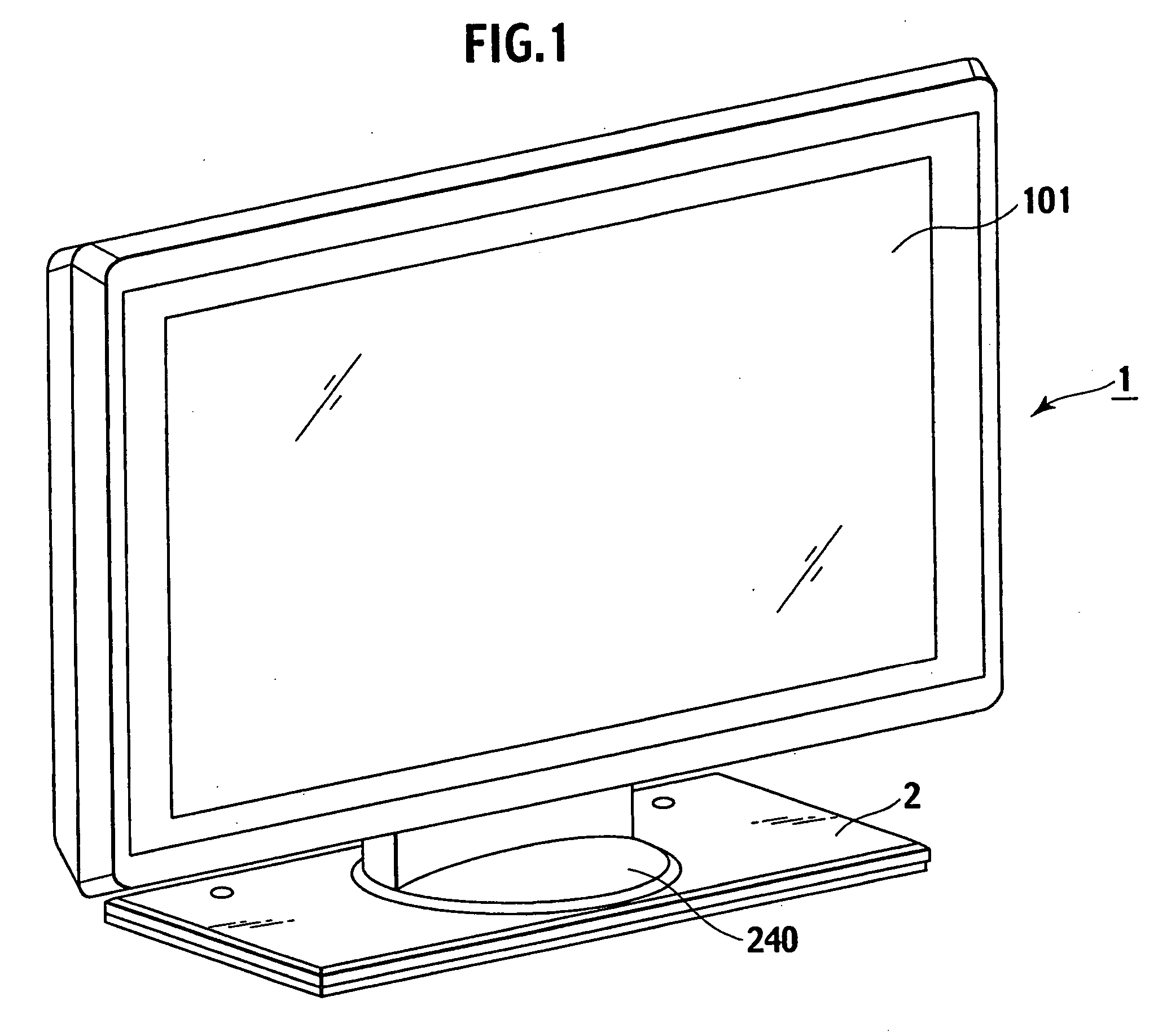
[0022] FIGS. 1 to 5 illustrate a first embodiment of the present invention. FIG. 1 is a perspective view of a display apparatus according to the first embodiment of the present invention. Referring to the figure, a display apparatus 1 is configured such that a display 101 is joined to and thereby supported by a support base 2. The display 101 in the display apparatus 1 is made up of a flat panel display device such as a PDP and displays a television image, etc. The following description assumes that the display 101 has a thin configuration.

[0023] The display 101 in the display apparatus 1 displays an image according to a signal received from tuner means (not shown) or video reproduction means (not shown). The support base 2 is provided with a turning means 240 thereon to two- or three-dimensionally turn the display 101 relative to the support base 2, allowing the viewing direction to be adjusted.

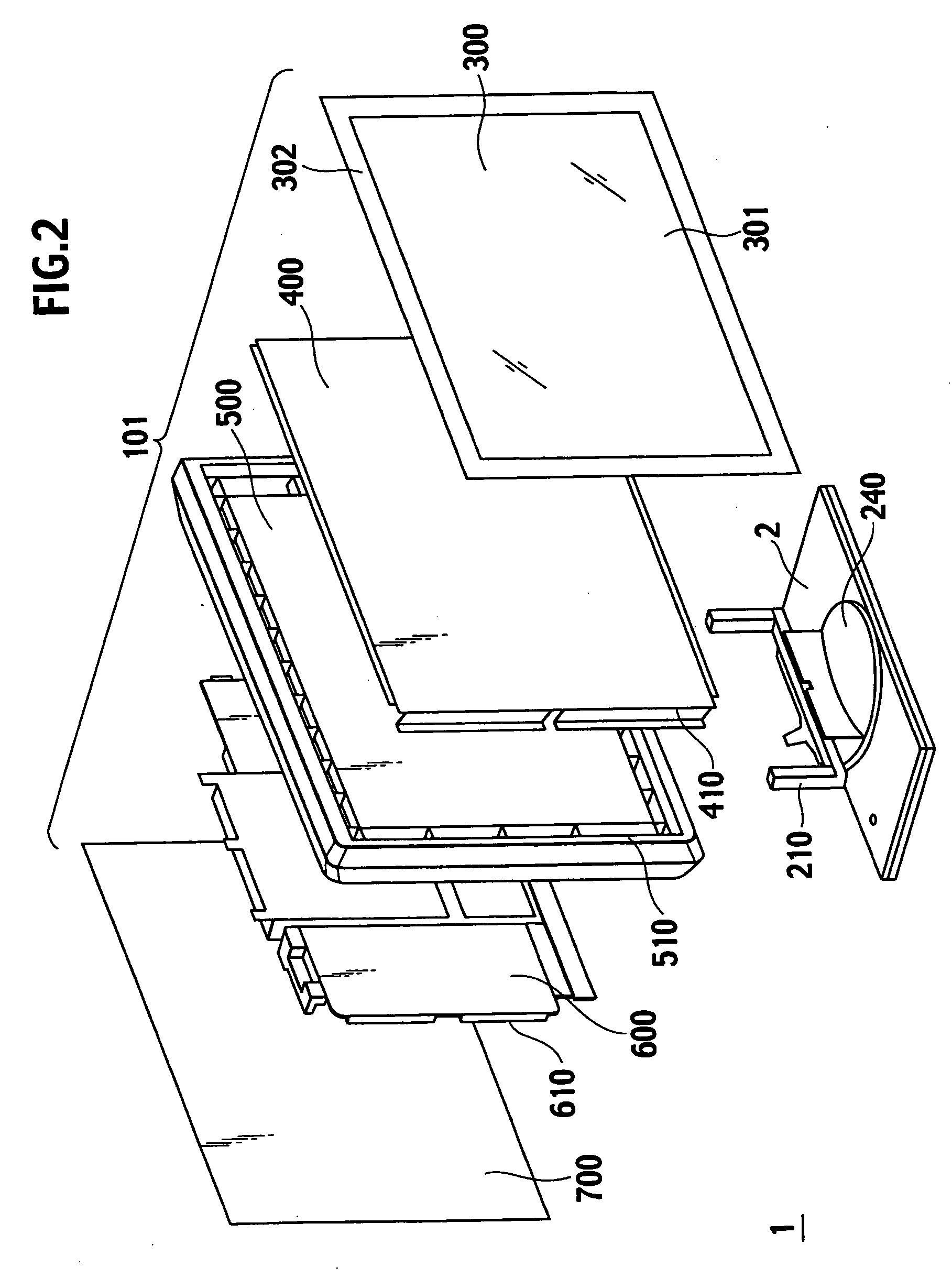
[0024]FIG. 2 is an exploded view showing the internal configuration of the display app...

second embodiment

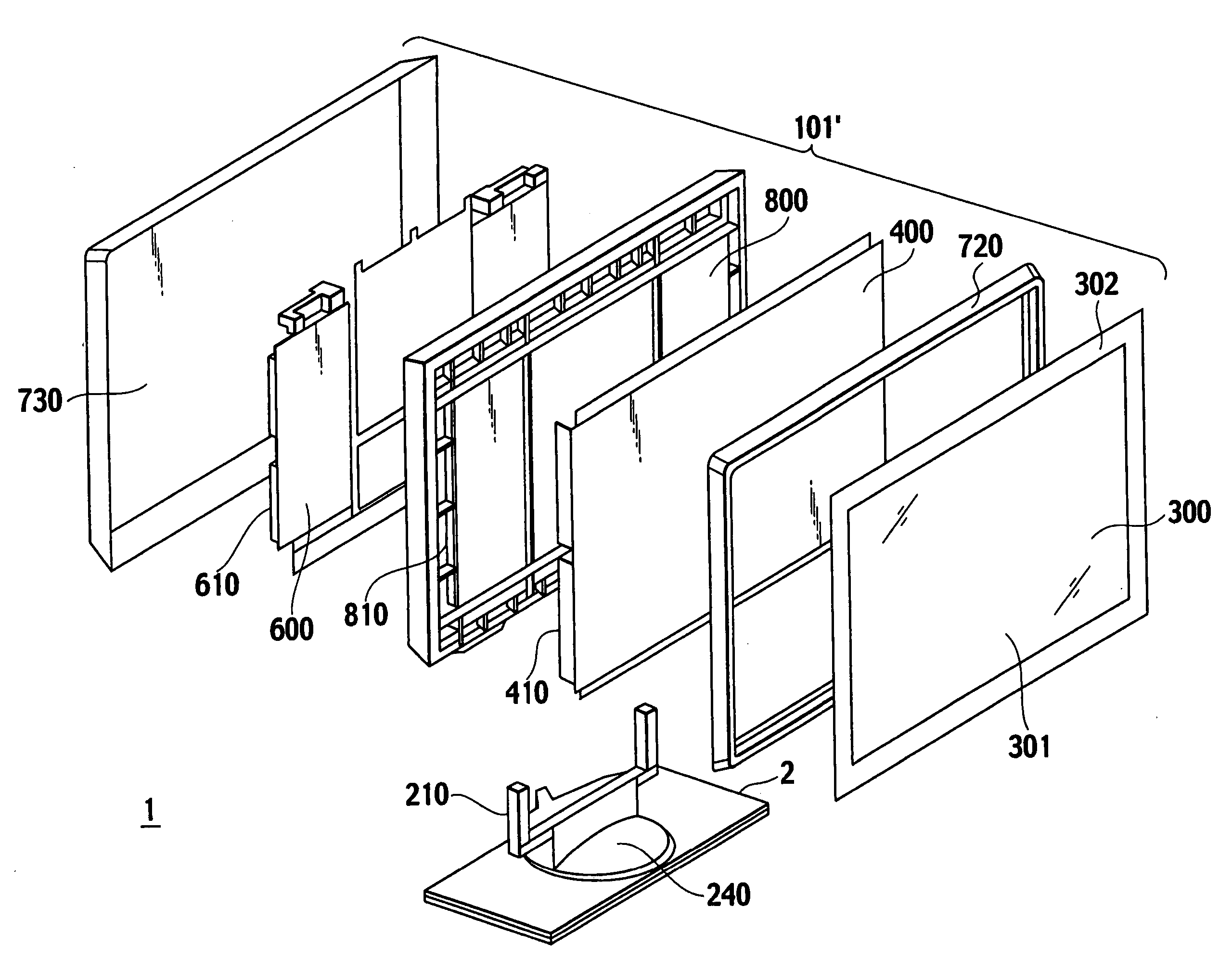
[0039] FIGS. 6 to 9 illustrate a display apparatus according to a second embodiment of the present invention. FIG. 6 is an exploded view showing the internal configuration of the display apparatus 1′ of the second embodiment.

[0040] The display apparatus 1′ is made up of: a display 101′ including a flat panel display device 400 (a PDP, etc.) for display; and a support base 2 supporting the display 101′. The display 101′ displays an image according to a signal received from tuner means (not shown) or video reproduction means (not shown). The support base 2 is provided with a turning means 240 thereon capable of two- or three-dimensionally turning the display 101′ relative to the support base 2, allowing the viewing direction to be adjusted. An optical filter member 300 is disposed on the front side of the display 101 to reduce reflection of external light. The optical filter member 300 is made up of a transparent portion 301 and a shielding portion 302, and the flat panel display dev...


PUM


Abstract

The present invention allows a display apparatus employing a flat panel display device to have a simple, low-cost construction. The display in the display apparatus of the present invention comprises: a flat panel display device; and a frame member including a frame-shaped first portion and a second portion that are formed integrally within the frame member, the first portion surrounding the circumference of the flat panel display device, the second portion being disposed inside the first portion and supporting the rear side of the flat panel display device thereon. The frame member may further include a third portion connectable to a support base, and the first to third portions may be integrally formed within the frame member.

Description

CLAIM OF PRIORITY [0001] The present application claims priority from Japanese application serial no. P2004-296652, filed on Oct. 8, 2004, the content of which is hereby incorporated by reference into this application. BACKGROUND OF THE INVENTION [0002] (1) Field of the Invention [0003] The present invention relates to the configuration of a display apparatus that uses a flat panel display device to display a television image, etc. [0004] (2) Description of the Related Art [0005] Display apparatuses such as TV receivers have been improved with the advance of display technology. For instance, efforts have been made to develop and manufacture thin display apparatuses by using a flat panel display device such as a liquid crystal display (hereinafter referred to as an “LCD”) panel or a plasma display panel (hereinafter referred to as a “PDP”). Furthermore, the size of display monitors using a flat panel display device has been increased; for example, large-size panels such as 50-inch (1...

Claims


Application Information

Patent Timeline
IPC IPC(8): G06F1/16H04N5/64
CPCG06F1/1601G06F2200/1612H04N5/64H04N5/72
Inventor SHIRAISHI, MIKIO
Owner HITACHI LTD
Why Eureka
Try Eureka