Bone conduction device

a bone conduction and microphone technology, applied in the direction of diaphragm damping, transducer details, electrical transducers, etc., can solve the problems of poor “loudness” of alternative methods and inability to obtain sufficient aerial vibrations, and achieve the effect of sufficient sound volume and clear sound

Inactive Publication Date: 2006-05-11
TEMCO JAPAN
View PDF14 Cites 68 Cited by
  • Summary
  • Abstract
  • Description
  • Claims
  • Application Information

AI Technical Summary

Benefits of technology

[0005] Since the conventional bone conduction speaker suffers from the above-mentioned problem, it is an object of the present invention to provide a bone conduction speaker, which is free from the problem inherent in the conventional bone conduction speaker. More particularly, it is an object of the present invention to provide a bone conduction speaker, which is capable of producing a sufficient amount of sound volume with respect to not only a bone conduction sound itself but also aerial vibrations when the bone conduction speaker is employed in a receiver of a bone conduction telephone set, thereby allowing the user to clearly catch the sound.

Problems solved by technology

However, heretofore, it is not possible for such alternative method to obtain a sufficient amount of aerial vibrations.
Due to this, the problem lies in that the alternative method is poor in “loudness” (i.e., the properties of sound in volume).

Method used


Image

  • Bone conduction device
  • Bone conduction device
  • Bone conduction device

Examples


Embodiment Construction

[0014] With reference to the accompanying drawings, embodiments of the present invention will be described. A bone conduction device of the present invention comprises a bone conduction speaker and a bone conduction microphone, both of which are substantially the same in construction. Due to this, only the bone conduction speaker will be described hereinbelow.

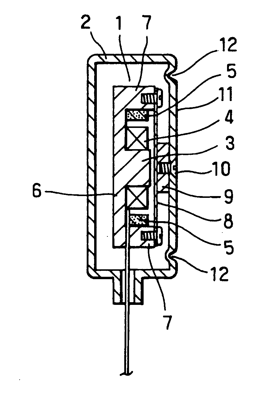
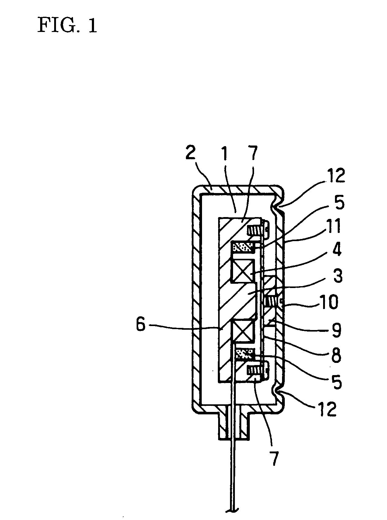
[0015]FIG. 1 is a longitudinal sectional view of an embodiment of the bone conduction speaker of the present invention. FIG. 2 is an enlarged longitudinal sectional view of anther embodiment of the bone conduction speaker of the present invention, illustrating an essential portion of the embodiment. The bone conduction speaker of the present invention is constructed of a bone conduction speaker unit 1 and a case 2 for packaging the speaker unit 1 therein.

[0016] In general, the speaker unit 1 is constructed of: a doughnut-shaped voice coil 4, which surrounds a central magnetic pole 3; a magnet 5 disposed on an inner peripheral...


PUM


Abstract

A bone conduction device which, when particularly employed in the receiver of a bone conduction telephone, is capable of obtaining a sufficient amount of sound as to not only a bone conduction sound but also an aerial vibration sound to ensure clear reception of the sound. The bone conduction device comprises a bone conduction device unit and a case receiving the device unit therein to serve as a vibration section and is characterized in that a compliance increasing means, such as a corrugation, is disposed along the peripheral edge of the vibrating surface of the case having the bone conduction device unit fixed thereto.

Description

TECHNICAL FIELD [0001] The present invention relates to a bone conduction device, and more particularly to a bone conduction speaker or a bone conduction microphone, wherein the bone conduction device is capable of keeping “loudness”, which is the properties of sound in volume of the device even when the bone conduction device is not held in abutting contact with the head portion of a user in use of a telephone set and like instruments in which the bone conduction device is incorporated. BACKGROUND ART [0002] For example, a bone conduction speaker is constructed of a bone conduction speaker unit 21 and a case 22 in which the speaker unit 21 is packaged. The speaker unit 21 is constructed of: a doughnut-shaped voice coil 24; a magnet 25 disposed on an inner peripheral surface of a peripheral wall 27 in a peripheral edge portion of a yoke 26; a vibrating plate 28 mounted on an upper surface of the peripheral wall 27; and, a vibrating block 29 fixedly mounted on an upper surface of the...

Claims


Application Information

Patent Timeline
Patent Type & Authority Applications(United States)
IPC IPC(8): H04R25/00H04R7/26H04R1/00H04R1/02H04R1/10
CPCH04R1/1091H04R2460/13H04R2499/11H04R9/066H04R25/606H04R1/00H04R1/02H04R7/26H04R13/00
Inventor KOBAYASHI, KAZUJI
Owner TEMCO JAPAN
Why Eureka
Try Eureka