Electroacoustic transducer and electroacoustic transduction system

a transducer and electroacoustic technology, applied in the direction of transducer diaphragms, electromechanical transducers, diaphragm construction, etc., can solve the problems of insufficient sound volume, improvement of frequency properties, and narrow frequency bands that can be reproduced with high acoustic quality and sufficient sound volume, etc., to achieve sufficient sound volume and high acoustic quality

Active Publication Date: 2017-12-21
FUJIFILM CORP
View PDF1 Cites 1 Cited by
  • Summary
  • Abstract
  • Description
  • Claims
  • Application Information

AI Technical Summary

Benefits of technology

[0035]According to the electroacoustic transducer of the present invention, the electroacoustic transduction system, and the electroacoustic transduction film, a sound with high acoustic quality is able to be reproduced with sufficient sound volume in a wide frequency band.

Problems solved by technology

However, it could be seen that since the electroacoustic transduction film described in JP2014-14063A is a single vibration plate, there is a problem that the frequency band that is able to be reproduced with high acoustic quality and sufficient sound volume is slightly narrow.
However, in the configuration in which the sound signal input to the speaker is corrected, the improvement of the frequency properties and the sound volume is insufficient.

Method used


Image

  • Electroacoustic transducer and electroacoustic transduction system
  • Electroacoustic transducer and electroacoustic transduction system
  • Electroacoustic transducer and electroacoustic transduction system

Examples


example 1

[0277]According to the method illustrated in FIGS. 6A to 6E described above, the transduction film 10 of the present invention illustrated in FIG. 5 was prepared.

[0278]First, cyanoethylated PVA (CR-V manufactured by Shin-Etsu Chemical Co., Ltd.) was dissolved in dimethylformamide (DMF) at the following compositional ratio. Thereafter, PZT particles were added to this solution at the following compositional ratio, and were dispersed by using a propeller mixer (rotation speed 2000 rpm), and thus a coating material for forming the piezoelectric layer 12 was prepared.[0279]PZT Particles 300 parts by mass[0280]Cyanoethylated PVA 30 parts by mass[0281]DMF 70 parts by mass

[0282]In addition, the PZT particles were obtained by sintering commercially available PZT raw material powder at 1000° C. to 1200° C. and thereafter crushing and classifying the resultant so as to have an average particle diameter of 5 μm.

[0283]On the other hand, the sheet-like materials 11a and 11c were prepared in whic...

example 6

[0311]As Example 6, an electroacoustic transduction system (see FIG. 11B) in which two electroacoustic transducers 100 (bent portion size 60 cm×5 cm) of Example 3 are provided and the vibration surfaces (the normal vectors of the bent portions at the center points) of the two electroacoustic transducers 100 were disposed to face the same direction, was prepared.

example 7

[0312]As Example 7, an electroacoustic transduction system (see FIG. 11C) in which four electroacoustic transducers 100 (bent portion size 60 cm×5 cm) of Example 3 are provided and the bent portions of the four electroacoustic transducers 100 are disposed to face the same direction, was prepared.

[0313]The sound pressure level and frequency properties of the prepared electroacoustic transduction systems were measured in the same manner as described above.

[0314]A graph for the comparison between the measurement results of the sound pressure level and frequency properties in Examples 6 and 7, and in the case of one electroacoustic transducer 100 of Example 3 (60 cm×5 cm) described above (see FIG. 11A), is shown in FIG. 12A.

[0315]As shown in FIG. 12A, it can be seen that in Example 6 having the two electroacoustic transducers 100, the sound pressure level is improved by about 6 dB in the entire frequency band, that is, by twice compared to Example 3. In addition, it can be seen that in ...


PUM


Abstract

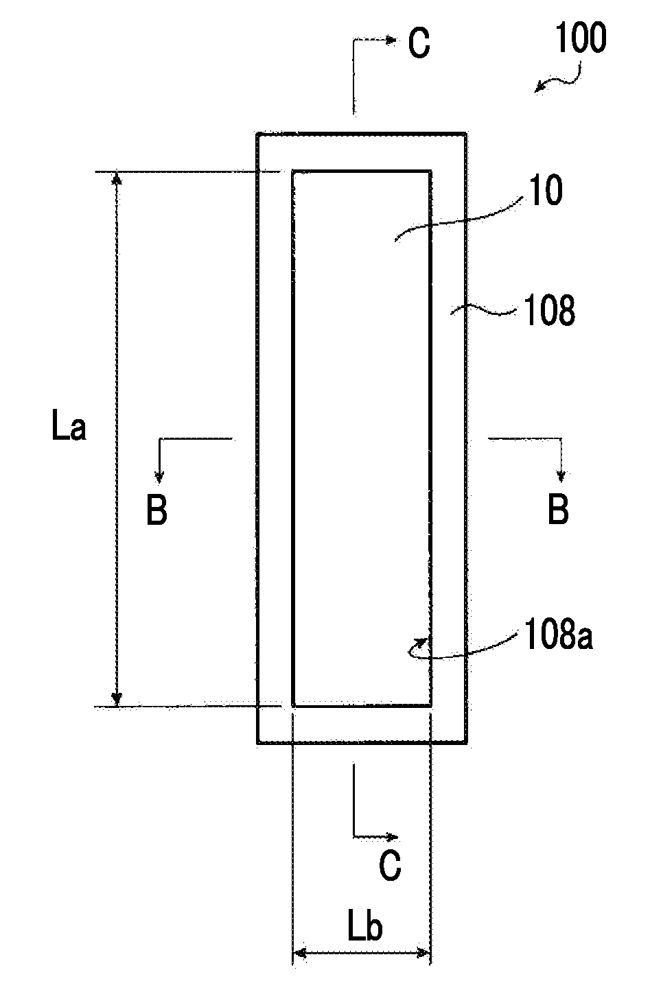
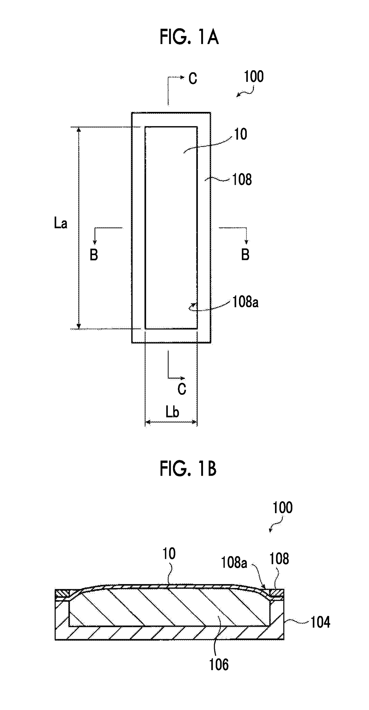
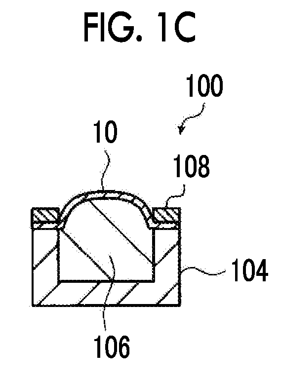
Provided are an electroacoustic transducer capable of stably reproducing a sound with high acoustic quality and widening a frequency band that is able to be reproduced, and an electroacoustic transduction system. In the electroacoustic transducer including: an electroacoustic transduction film including a polymer composite piezoelectric body in which piezoelectric body particles are dispersed in a viscoelastic matrix formed of a polymer material having viscoelasticity at a normal temperature, and two thin film electrodes laminated on both surfaces of the polymer composite piezoelectric body; and an elastic supporter which is disposed to be closely attached to one principal surface of the electroacoustic transduction film so as to cause the electroacoustic transduction film to be bent, a bent portion of the electroacoustic transduction film has a quadrangular shape, a length of a short side of the bent portion is less than or equal to 10 cm, and a length of a long side thereof is greater than or equal to 30 cm.

Description

CROSS-REFERENCE TO RELATED APPLICATIONS[0001]This application is a Continuation of PCT International Application No. PCT / JP2016 / 054739 filed on Feb. 18, 2016, which claims priority under 35 U.S.C. §119(a) to Japanese Patent Application No. 2015-039267 filed on Feb. 27, 2015. The above application is hereby expressly incorporated by reference, in its entirety, into the present application.BACKGROUND OF THE INVENTION1. Field of the Invention[0002]The present invention relates to an electroacoustic transducer used for an acoustic device such as a speaker, and an electroacoustic transduction system.2. Description of the Related Art[0003]In response to thinning of displays such as liquid crystal displays and organic electroluminescence (EL) displays, speakers used in such thin displays are also required to be lighter and thinner. As such a lightweight and thin speaker, it is considered to adopt a sheet-like piezoelectric film having a property that stretches and contracts in response to ...

Claims


Application Information

Patent Timeline
Patent Type & Authority Applications(United States)
IPC IPC(8): H04R17/00H04R7/12H04R7/16H04R31/00
CPCH04R7/16H04R7/122H04R31/003H04R17/00H04R2307/025H04R1/02H04R1/40H04R7/12H04R17/005
Inventor MIYOSHI, TETSU
Owner FUJIFILM CORP
Why Eureka
Try Eureka