Magnetostrictive actuator
- Summary
- Abstract
- Description
- Claims
- Application Information
AI Technical Summary
Benefits of technology
Problems solved by technology
Method used
Image
Examples
Embodiment Construction
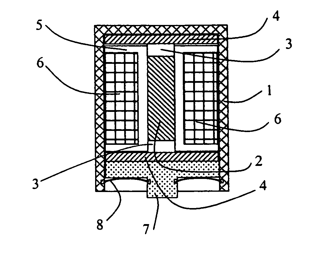
[0065] The magnetostrictive actuator shown in FIG. 1 comprises a casing 1, for example of a non-magnetic material, in which is located a rod 2 of giant magnetostrictive material (which for convenience may comprise two pieces of the GMM, end-to-end), with a non-magnetic spacer 3, for example of aluminium or a ceramic material capable of transmitting force, disposed at each end thereof to space the GMM rod 2 from a pair of disc magnets 4 of substantially greater diameter than the width of the rod. A plastics core 5 serves to locate and hold the GMM rod 2 and spacers, and carries an electromagnetic winding 6 which is connected via wires (not shown) to a separate energising signal source. A foot 7 transmits the force produced by the actuator to the desired location. A spring clip 8 held in grooves around the inside of the casing 1 and the foot 7 holds the assembly together and imposes a mechanical pre-stress on the GMM rod 2.
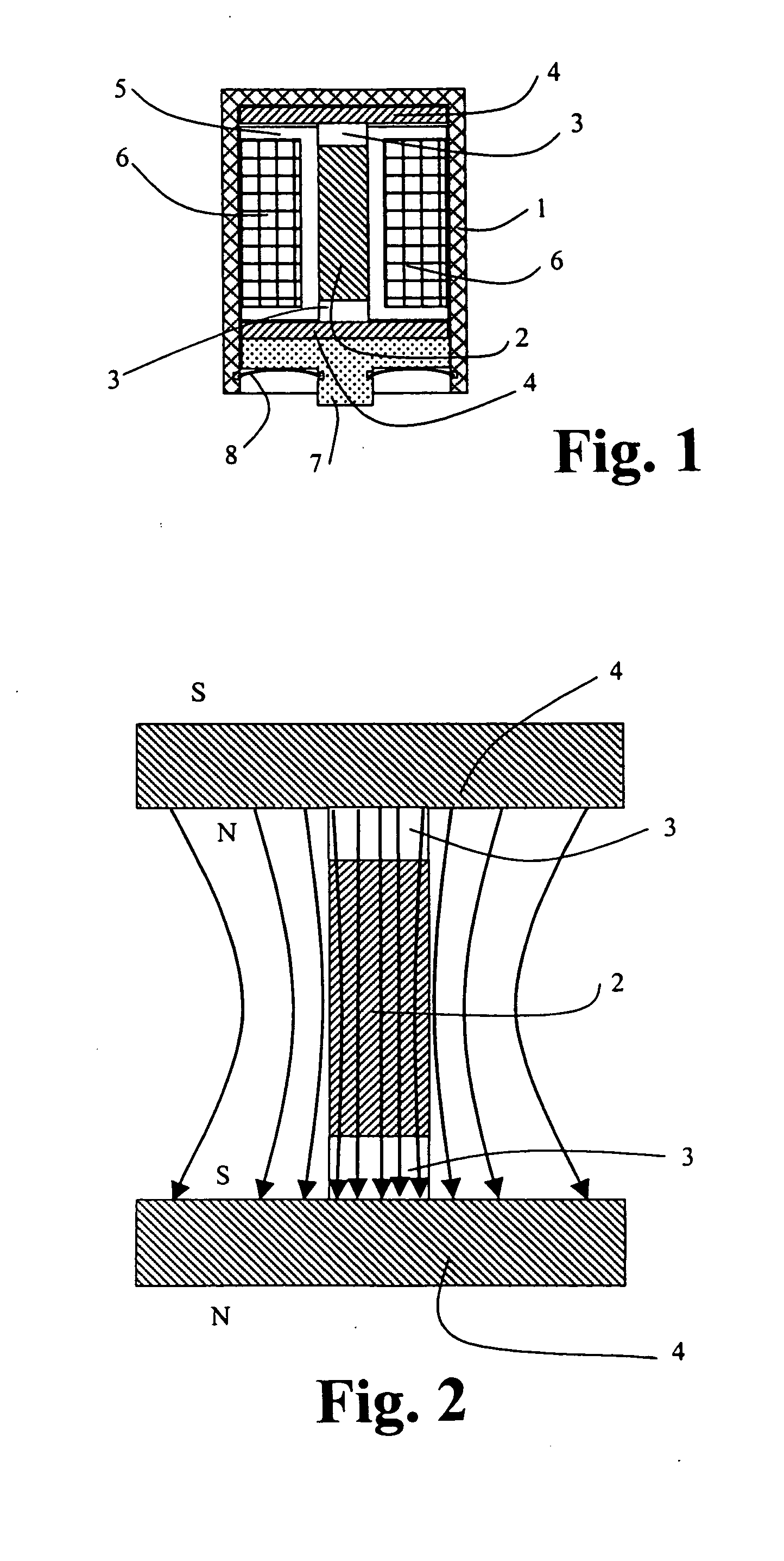
[0066] As may be seen more clearly from FIG. 2, by selecting ...
PUM
 Abstract
Description
Claims
Application Information
 - R&D
- Intellectual Property
- Life Sciences
- Materials
- Tech Scout
- Unparalleled Data Quality
- Higher Quality Content
- 60% Fewer Hallucinations
Browse by: Latest US Patents, China's latest patents, Technical Efficacy Thesaurus, Application Domain, Technology Topic, Popular Technical Reports.
© 2025 PatSnap. All rights reserved.Legal|Privacy policy|Modern Slavery Act Transparency Statement|Sitemap|About US| Contact US: help@patsnap.com


