Guide shaft holding mechanism and disk device including the guide shaft holding mechanism

Inactive Publication Date: 2006-06-01
ORION ELECTRIC CO LTD
View PDF13 Cites 2 Cited by
  • Summary
  • Abstract
  • Description
  • Claims
  • Application Information

AI Technical Summary

Benefits of technology

[0009] Thus, the present invention has an object to provide a guide shaft holding mechanism which makes it possible to downsize and miniaturize the device by reducing a

Problems solved by technology

However, the above described guide shaft holding mechanism positions and holds the guide shaft with respect to the chassis to which the pickup is simply assembled, but the guide shaft for pickup which is used for a disk drive is important in accuracy in the height direction, and unless the position in the height direction is adjusted to a proper value, there occur various kinds of problems that an optical axis of a laser beam emitted from the optical pickup inclines with respect to the rea

Method used


Image

  • Guide shaft holding mechanism and disk device including the guide shaft holding mechanism
  • Guide shaft holding mechanism and disk device including the guide shaft holding mechanism
  • Guide shaft holding mechanism and disk device including the guide shaft holding mechanism

Examples


Embodiment Construction

[0021] Hereinafter, an example of the best mode for carrying out a disk device including a guide shaft holding mechanism according to the present invention will be described by referring to the drawings, but the present invention is not limited to only an embodiment of the present invention.

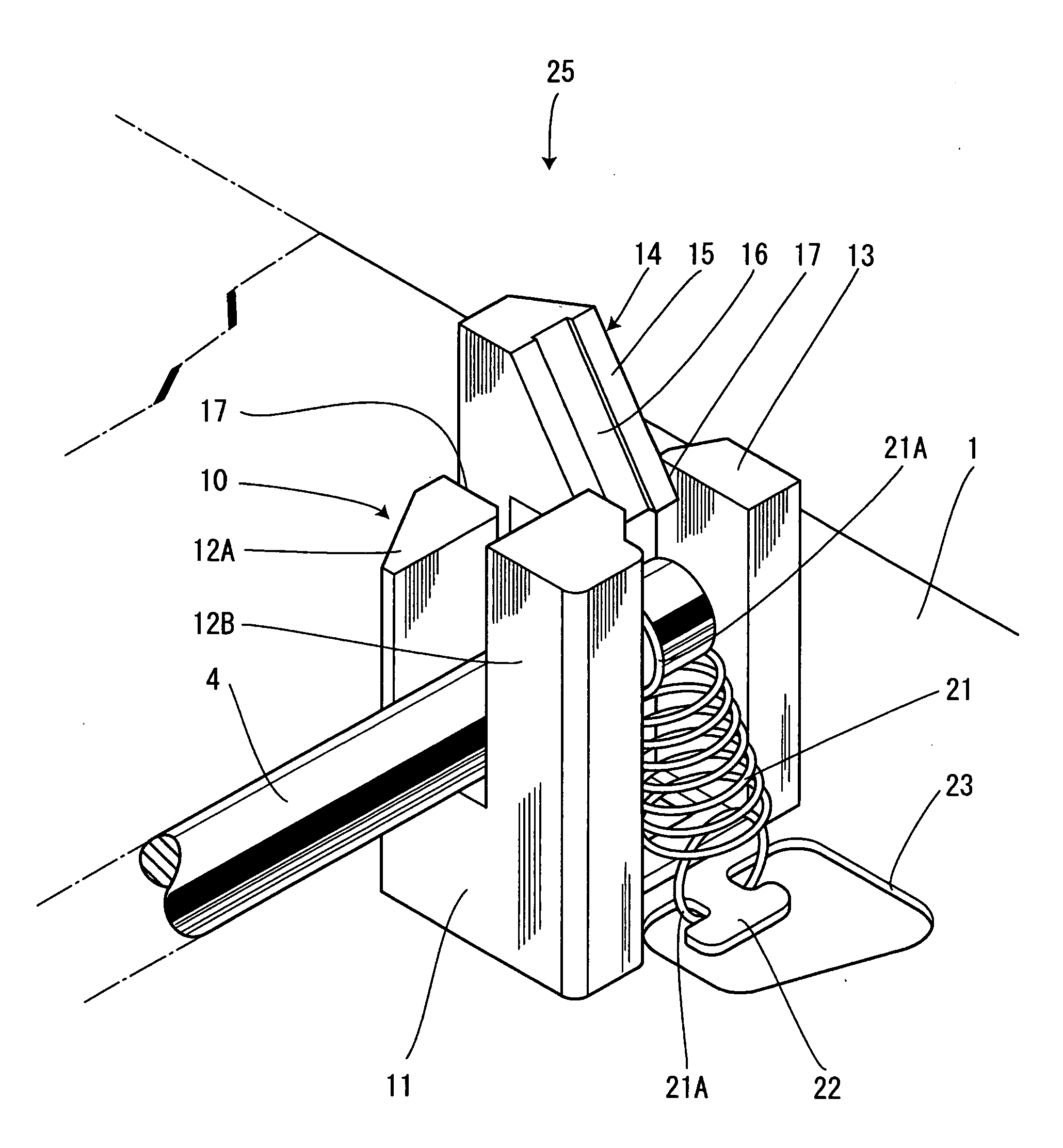
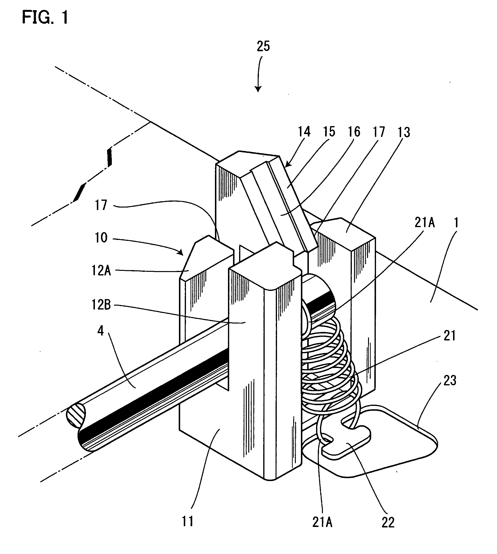
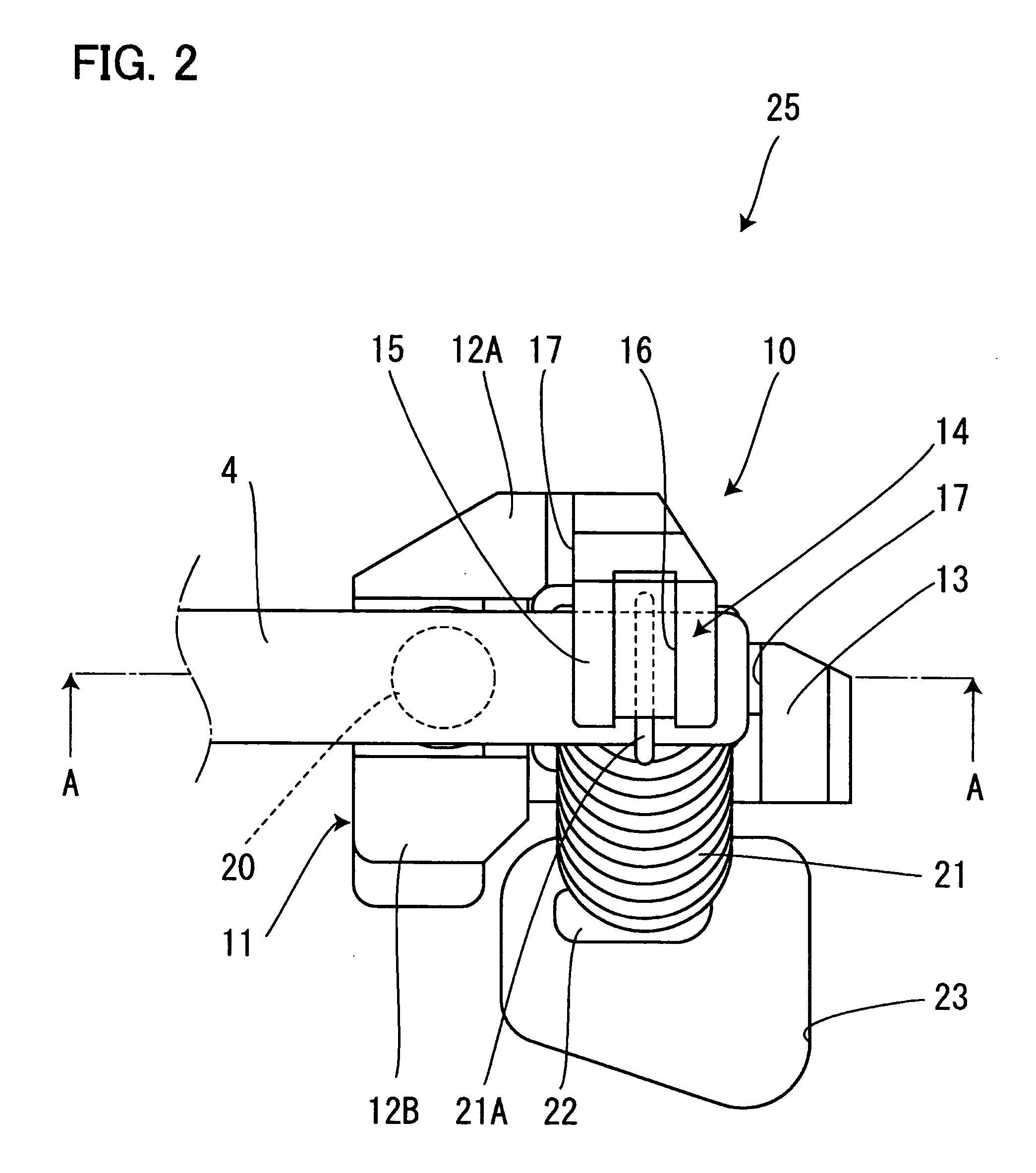
[0022]FIG. 1 is a perspective view showing a guide shaft holding mechanism of the present invention, FIG. 2 is a plane view of the guide shaft holding mechanism, FIG. 3 is a sectional view taken along the A to A line in FIG. 2, and FIG. 4 is a general plane view with a guide shaft being mounted thereto.

[0023] As shown in the drawings, reference numeral 1 denotes a chassis on which a pickup 3 of the disk device is mounted, and which is formed by folding a metallic thin plate, a pair of left and right guide shafts 4 and 5 for guiding the above described pickup 3 including a pickup lens 2 are assembled to the chassis 1. In order to hold both end portions of the guide shafts 4 and 5, a holding part...


PUM


Abstract

To make it possible to downsize a device by reducing an occupied space on a chassis occupied by a holding mechanism of a guide shaft as much as possible. A support part 10 is constructed by integrally molding guide walls 12A, 12B which restrict movement of a guide shaft 4 in a radial direction, a stopper part 13 which restricts movement of the guide shaft in a thrust direction and a hook part 14 which restricts slipping-off of the guide shaft 4. A coil spring 21 is provided at a position opposed to the hook part 14 disposed between the guide walls 12A and 12B and the stopper part 13. Thereby, the holding mechanism 25 of the guide shaft 4 including the support part 10 and the coil spring 21 is organized to be compact, and the occupied space of the holding mechanism 25 in a chassis 1 is reduced.

Description

[0001] The present application is based on and claims priority of Japanese patent application No. 2004-346467 filed on Nov. 30, 2004, the entire contents of which are hereby incorporated by reference. BACKGROUND OF THE INVENTION [0002] 1. Field of the Invention [0003] The present invention relates to a guide shaft holding mechanism and a disk device including the guide shaft holding mechanism, and particularly relates to a holding mechanism of a guide shaft, which moves in parallel a pickup which records information into a storage medium such as an optical disk and / or reproduces information recorded in the storage medium, and a disk device including the guide shaft holding mechanism. [0004] 2. Description of the Related Art [0005] For example, in a disk device, a pickup is included, and the pickup moves in parallel in a radius direction of an optical disk along a pair of guide shafts fixed to a chassis to record information into the optical disk and / or reproduces information recorde...

Claims


Application Information

Patent Timeline
IPC IPC(8): G11B33/02
CPCG11B7/08582G11B21/083
Inventor AZAI, KOUJI
Owner ORION ELECTRIC CO LTD
Why Eureka
Try Eureka