Starting and controlling speed of a two spool gas turbine engine

a gas turbine engine and two-spool technology, applied in the direction of engine control, machine/engine, hot gas positive displacement engine plants, etc., can solve the problems of high load inertia, low efficiency, and low operation reliability, and achieve the effect of preventing compressor surg

Inactive Publication Date: 2006-07-13
HONEYWELL INT INC
View PDF8 Cites 105 Cited by
  • Summary
  • Abstract
  • Description
  • Claims
  • Application Information

AI Technical Summary

Benefits of technology

[0014] In another aspect of the present invention, a method for preventing compressor surge, overtemperature and overspeed in a two spool gas turbine engine, the two spool gas turbine engine having a generator attached to a power turbine shaft driven by a hot gas air flow generated by a gas generator, comprises measuring a condition reflective of a change in an external electric load on the generator; and adjusting the speed of the gas generator shaft with a motor / generator rotationally attached to the gas generator shaft.

Problems solved by technology

Very often, the load has a high inertia and engine response to load changes is relatively slow.
Because the gas turbine engine cannot respond as quickly as desired, a rapid load transient may cause operational and reliability problems, such as compressor surge and high turbine temperature.
When a load is suddenly removed, the speed of the power turbine spool may increase above the desirable operating maximum speed, resulting in an overspeed condition.
Rapid load changes can cause operational and reliability problems as described above.
The Mose invention, however, requires the availability of external (utility) power and does not address the problem of controlling the shaft speed of a two spool gas turbine engine, especially during generator load transients.
The Birch invention however cannot be applied to applications where the gas turbine engine is the only primary source of electrical power and limiting the electrical load is not practical.

Method used


Image

  • Starting and controlling speed of a two spool gas turbine engine
  • Starting and controlling speed of a two spool gas turbine engine
  • Starting and controlling speed of a two spool gas turbine engine

Examples


Embodiment Construction

[0019] The following detailed description is of the best currently contemplated modes of carrying out the invention. The description is not to be taken in a limiting sense, but is made merely for the purpose of illustrating the general principles of the invention, since the scope of the invention is best defined by the appended claims.

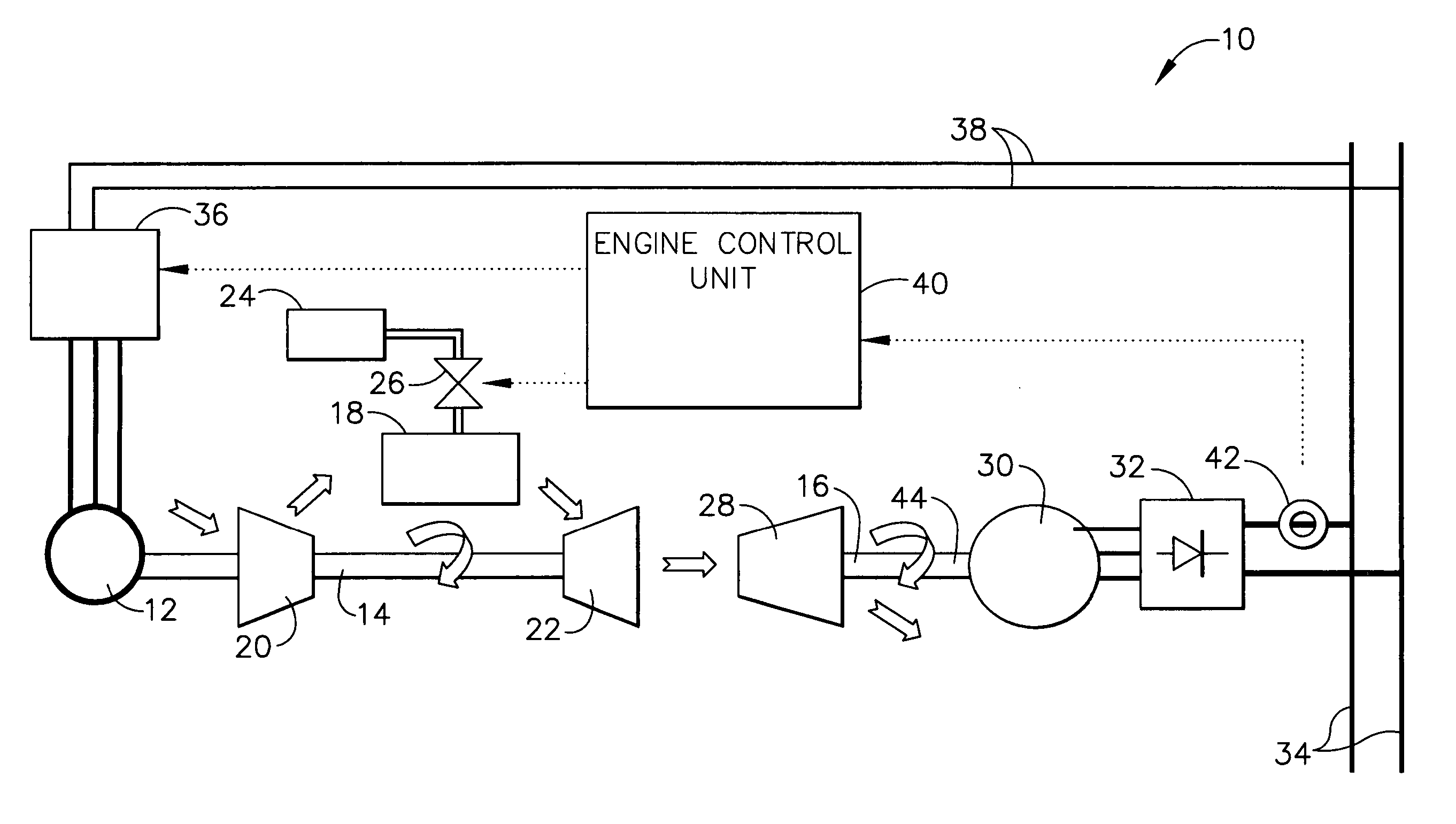
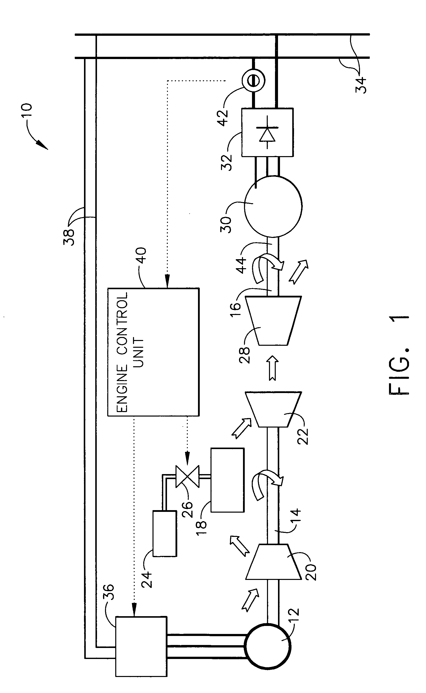
[0020] Broadly, the present invention provides a small motor / generator which may be added to the gas generator spool of a gas turbine engine to quickly adjust the compressor speed and airflow to compensate for external load changes. The motor / generator may add or subtract power to the gas generator spool whenever a significant load change occurs, thereby reducing the response time of the system to sudden load changes. Unlike conventional engine speed adjustment means, which typically rely on a control of the flow of fuel to the gas turbine engine, the present invention results in a more immediate adjustment of the gas turbine compressor speed, which a...


PUM


Abstract

Two spool gas turbine engines are often used to drive variable speed loads, such as an electric generator, or the fan / propeller of aircraft engines. The gas turbine engine must be designed to withstand transient speed and temperature conditions which are encountered when sudden changes to the load on the generator, fan, or propeller occur. By adding a relatively small motor / generator to the gas generator spool of the gas turbine engine, the compressor speed and airflow can be quickly adjusted to compensate for external load changes. This reduces the severity and duration of the transient conditions, resulting in decreased operation and reliability problems such as overspeed, compressor surge, and high turbine temperature. The motor / generator may also be used as an engine starting device.

Description

BACKGROUND OF THE INVENTION [0001] The present invention relates generally to starting and controlling the speed of a two spool gas turbine engine and, in particular, to providing a motor / generator to add or subtract power to the gas generator spool of a two spool gas turbine engine. [0002] Two spool gas turbine engines are often desirable solutions as prime movers for various transportation applications. These engines consist of a gas generator spool and a power turbine spool. Most of the output power of the engine is taken by mechanically connecting a load to the power turbine spool. Very often, the load has a high inertia and engine response to load changes is relatively slow. [0003] For example, when the load connected to the power turbine spool consists of an electrical generator, the electrical loads connected to the generator may be suddenly applied or removed. Because the gas turbine engine cannot respond as quickly as desired, a rapid load transient may cause operational an...

Claims


Application Information

Patent Timeline
Patent Type & Authority Applications(United States)
IPC IPC(8): F02C9/00
CPCF02C7/275F02C9/00F05D2270/091
Inventor MCGINLEY, RAY M.LUEBS, ALAN B.
Owner HONEYWELL INT INC
Why Eureka
Try Eureka