Twin Scroll Turbocharger with Waste Heat Recovery

a turbocharger and waste heat technology, applied in the direction of engines, mechanical equipment, machines/engines, etc., to achieve the effect of maximizing engine torque, preventing compressor surge, and increasing air mass flow through the compressor

Inactive Publication Date: 2020-09-10
MENDLER EDWARD CHARLES
View PDF0 Cites 0 Cited by
  • Summary
  • Abstract
  • Description
  • Claims
  • Application Information

AI Technical Summary

Benefits of technology

[0012]According to the present invention, bypass air from downstream of the compressor is directed into a heat exchanger that draws heat from the exhaust gas of the engine. The bypass air does not include fuel, and instead is heated by the exhaust gas in the heat exchanger. The bypass duct enables air mass flow through the compressor to be increased, thereby preventing compressor surge at low engine speeds. The turbocharge entry scroll. The ss air is fed into the first scroll after being heated in the heat exchanger, and the engine exhaust gas is fed into the second scroll. Both turbine scrolls are used at low engine speeds for maximizing engine torque. Use of two scrolls enables the blowdown impulse energy of the exhaust gas to be retained within the exhaust manifold prior to entry into the turbine. In more detail the exhaust gas does not backflow into the bypass duct and loose working pressure. Engine efficiency is also increased by using the exhaust energy to heat the bypass air instead of combusting additional fuel. There is no explosive combustion of fuel and bypass air upstream of the turbine that would create noise and decrease turbocharger life. The heated bypass air flowing into the turbine increases turbine power leading to higher turbocharger boost pressure ratios.
[0013]A control valve may optionally be used to open both scrolls for exhaust flow, and close of the bypass duct at high engine speeds where use of the bypass duct is not needed. Flow of exhaust gas into both of the scrolls at high engine speeds enables higher maximum engine power output levels to be attained. In more detail, the first scroll is used for the bypass air during low speed engine operation, and the second scroll is used for exhaust gas at all engine speeds. Use of separate scrolls for the bypass air and exhaust gas prevents exhaust pressure waves from propagating into the bypass duct and Intake air system of the engine. At high engine speeds the first scroll or bypass scroll may be closed. Optionally the bypass scroll may be unused during high engine speeds, or a valve may be used to open the bypass scroll for receiving exhaust gas so that both the first and second scroll receive exhaust gas during high speed engine operation. Use of both scrolls for exhaust gas enables higher engine power levels to be achieved.
[0014]The present invention enables high boost pressures to be attained across a wide range of engine speeds. Yet another advantage of the present invention is that it does not include a combustor or a secondary fuel delivery system. The fueling needs can be fully met with the existing fuel injection system. A significant advantage of the present invention is that use of waste heat recovery through the exhaust gas heat exchanger provides improved engine efficiency relative to other engines operating at similar speed and brake mean effective pressure. Another advantage of the present invention is that the heated bypass air and exhaust gas from the engine enter the turbine through separate scrolls. Use of separate scrolls prevents the exhaust gas from back flowing into the bypass duct. Another advantage of the turbocharging system is that it has a relatively low cost. An expensive heat exchanger is not required for effective operation of the turbocharger system. High boost pressures can be attained with the present invention across a wide engine speed range. Prospective applications for the technology include long haul diesel trucks where steady state fuel economy can be improved through the waste heat recovery, and light duty cars and trucks where fuel economy can be significantly improved zing.
[0015]In current production engines it is common to employ a rich fuel to air mixture during high load engine operating conditions in order to internally cool the engine and suppress detonation. According to an embodiment of the present invention, under high loads the fuel injection system of the engine injects excess fuel for combustion. Enrichment levels are similar to current production engines. The unburned excess fuel in the exhaust gas combines with the bypass air and undergoes catalytic combustion in the catalytic converter. The catalytic combustion increases the temperature of the exhaust gas entering the heat exchanger, causing the temperature of the bypass air entering the turbine to become even hotter. The increase of bypass air temperature increases the power output of the turbine causing the compressor to spin faster and generate higher boost pressures. In addition to increasing turbocharger boost pressure, hydrocarbon emissions are reduced because the added air provides the needed oxygen for complete combustion of the fuel. The turbine is upstream and isolated from the catalytic combustion. Effective waste heat recovery in the heat exchanger minimizes the degree and frequency of enrichment.
[0016]Advantages of the present invention include increased boost pressure at low engine speeds without compromising maximum engine power output; increased engine efficiency at some engine power levels due to the waste heat recovery of the heat exchanger; lower hydrocarbon emissions during high load conditions due to bypass air being provided for complete combustion of the fuel during rich engine operating conditions; and a relatively low cost.

Problems solved by technology

An expensive heat exchanger is not required for effective operation of the turbocharger system.

Method used


Image

  • Twin Scroll Turbocharger with Waste Heat Recovery
  • Twin Scroll Turbocharger with Waste Heat Recovery
  • Twin Scroll Turbocharger with Waste Heat Recovery

Examples


Embodiment Construction

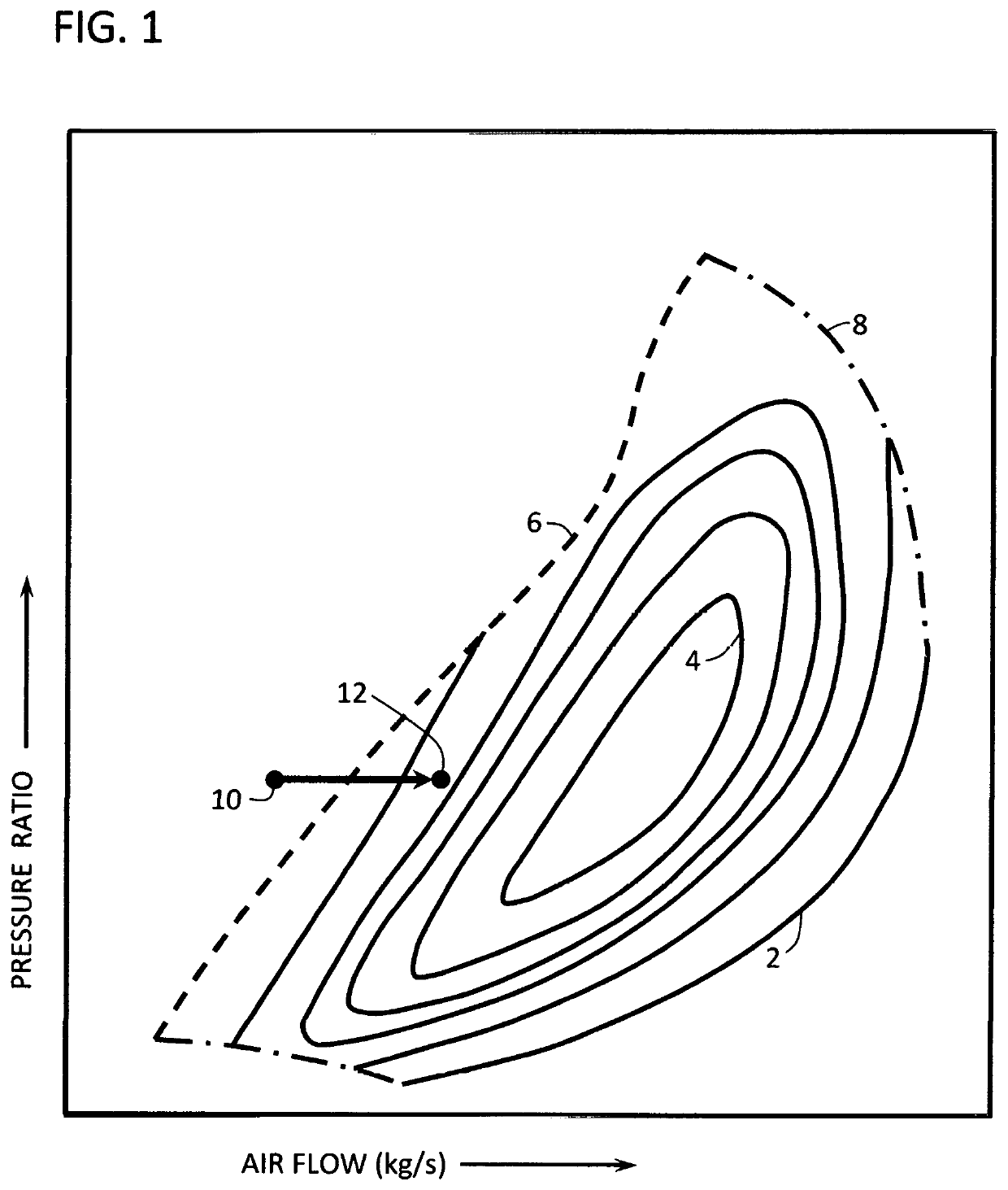
[0026]FIG. 1 is intended to diagrammatically illustrate air flow through a turbocharger compressor according to the present invention, and in more detail FIG. 1 is intended to diagrammatically illustrate a portion of the present invention. Air mass flow is shown on the horizontal axis of the FIG. 1 diagram, and compressor pressure ratio in shown on the vertical axis of the FIG. 1 diagram. Constant efficiency compressor contour lines 2 are plotted in the FIG. 1 diagram, with contour line 4 indicating the area of highest compressor operating efficiency. The surge limit line 6 indicates the maximum pressure ratio that can be achieved by the compressor for a given air mass flow rate. Compressor operating conditions to the left of surge limit line 6 will encounter surge, and are therefore unacceptable. Operating conditions to the right of surge limit line 6 will not encounter surge, and may be used within the operating speed limits of the turbocharger. The maximum speed limit line 8 of t...


PUM


Abstract

Bypass air from downstream of the compressor is directed into a heat exchanger that draws heat from the exhaust gas of the engine. The bypass air does not include fuel, and instead is heated by the exhaust gas in the heat exchanger. The bypass duct enables air mass flow through the compressor to be increased, thereby preventing compressor surge at low engine speeds. The turbocharger turbine includes a dual entry scroll. The bypass air is fed into the first scroll after being heated in the heat exchanger, and the engine' exhaust gas is fed into the second scroll. Use of two scrolls enables the blowdown impulse energy of the exhaust gas to be retained within the exhaust manifold prior to entry into the turbine, thereby providing improved turbocharger response and preventing backflow of exhaust gas into the bypass duct. Using the exhaust energy to heat the bypass air instead of combusting additional fuel leads to increased engine efficiency.

Description

[0001]This application relates to Provisional Application No. 62 / 386,901 having a filing date of Dec. 14, 2015, Provisional Application No. 62 / 391,136 having a filing date of Apr. 19, 2016 and Provisional Application No. 62 / 493,881 having a filing date of Jul. 18, 2016.BACKGROUND OF THE INVENTION[0002]Engine downsizing is viewed by US and foreign automobile manufacturers as one of the best options for improving passenger car and light duty truck fuel economy. While this strategy has already demonstrated a degree of success, downsizing and fuel economy gains are currently limited by the ability of low-cost turbocharging systems to provide high boost pressures over a wide range of engine speeds.[0003]At low engine speeds turbochargers are generally unable to deliver high boost pressures because of surge and insufficient turbine power. When boost pressures become too great the inertial force of the air exiting the compressor is overcome by the high pressure air downstream. When this oc...

Claims


Application Information

Patent Timeline
Patent Type & Authority Applications(United States)
IPC IPC(8): F02B37/16F01N3/10F02D23/02
CPCF01N3/10F02D23/02F02B37/162F01N3/0205F01N3/055F02B37/025F02B37/168F02B37/20F02B2037/125Y02T10/12
Inventor MENDLER, EDWARD CHARLES
Owner MENDLER EDWARD CHARLES
Why Eureka
Try Eureka