Filter connector

a filter connector and connector technology, applied in the direction of coupling device connection, electrical discharge lamp, coupling device details, etc., can solve the problems of high cost, time-consuming, and add considerably to the cost of the connector, and achieve the effect of convenient mounting

Inactive Publication Date: 2006-07-20
MOLEX INC
View PDF2 Cites 19 Cited by
  • Summary
  • Abstract
  • Description
  • Claims
  • Application Information

AI Technical Summary

Benefits of technology

[0006] According to one aspect of the invention, biasing means are provided between the shorting bar and the filters to bias the filters against the terminals. Preferably, the biasing means is integral with the shorting bar. As disclosed herein, the shorting bar is stamped and formed of sheet metal material, and the biasing means comprise an integral leaf spring portion of the bar engageable with each filter. Therefore, the filters can be easily mounted fairly loosely into their respective passage, and the biasing means or leaf spring is effective to tighten the assembly.

Problems solved by technology

One of the problems with such filter connectors simply is their cost.
These steps are time consuming and require assembly tooling, all of which adds considerably to the cost of the connectors.
All of these assembly operations require relatively expensive assembly tooling.

Method used


Image

  • Filter connector
  • Filter connector
  • Filter connector

Examples


Embodiment Construction

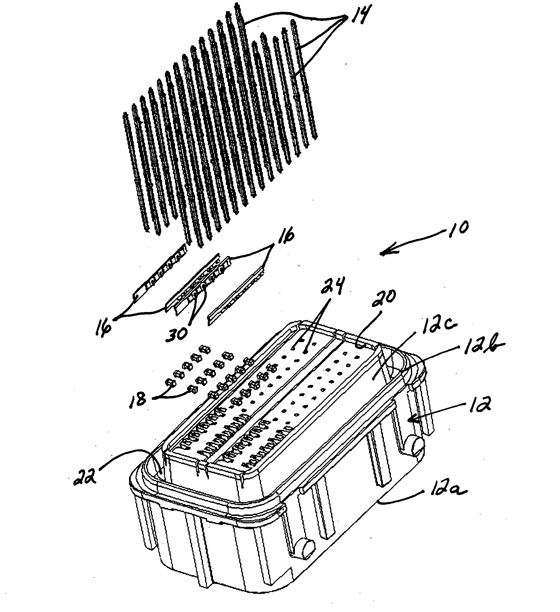
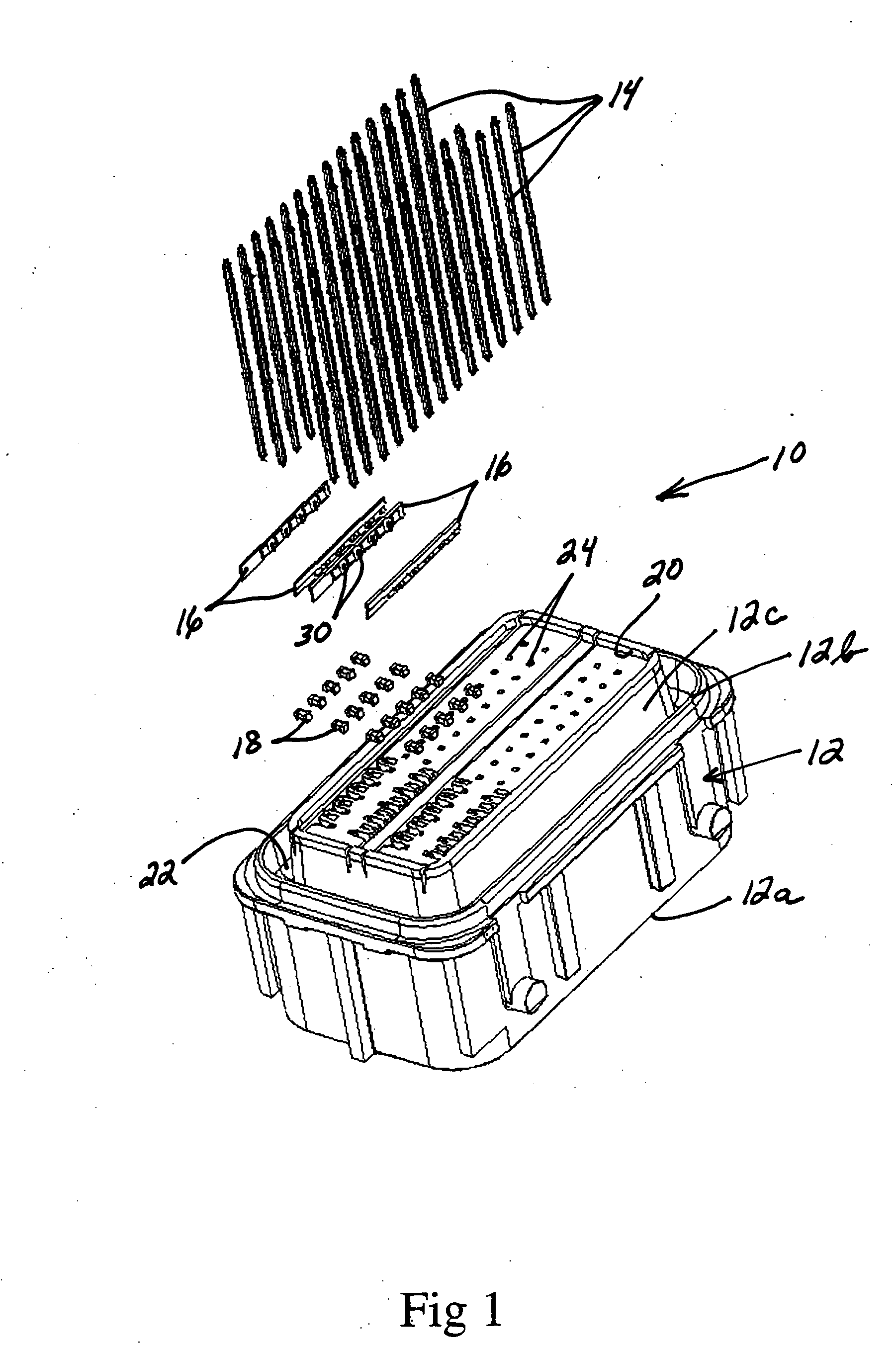
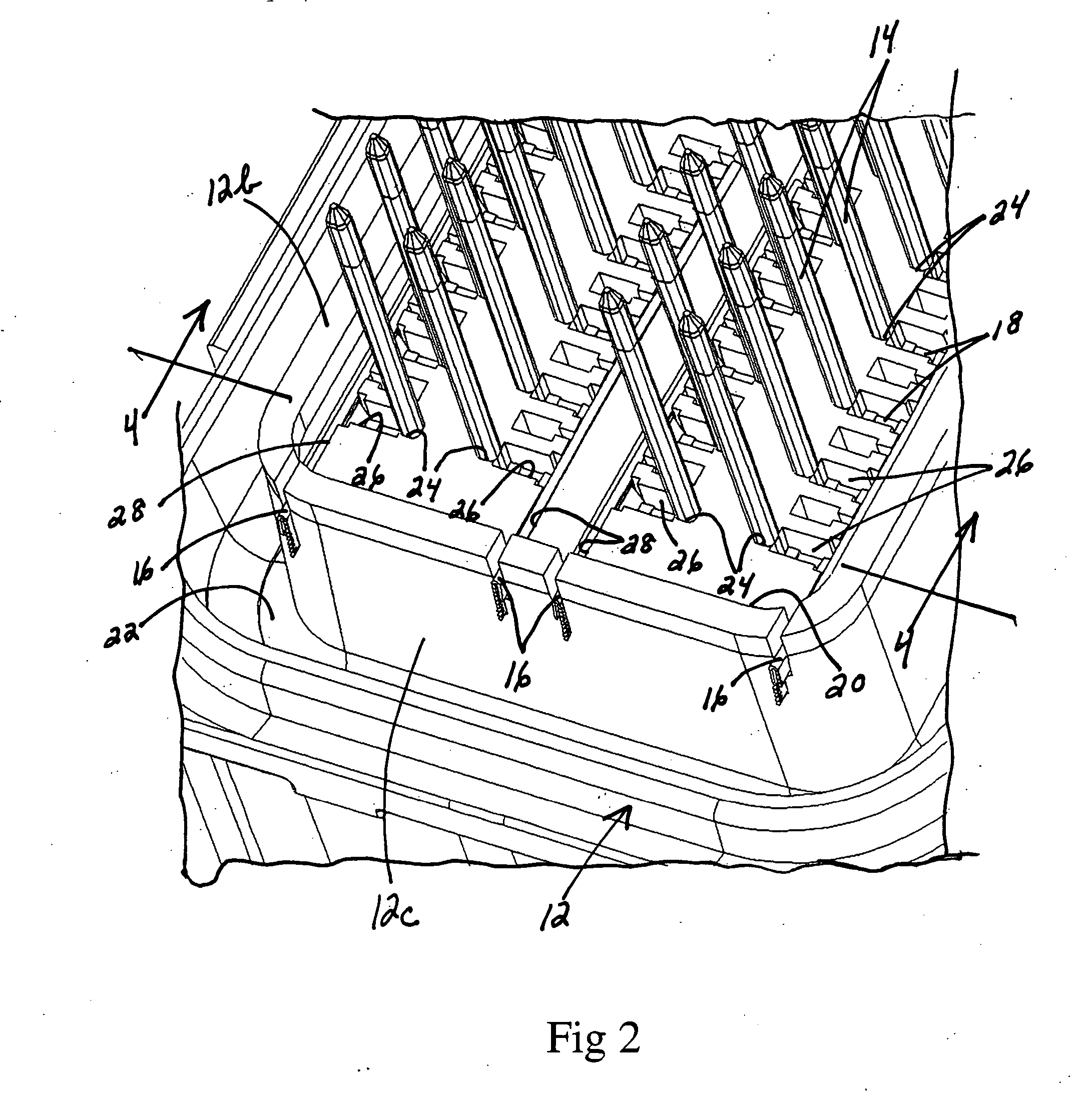
[0015] Referring to the drawings in greater detail, and first to FIG. 1, the invention is embodied in a filtered electrical connector, generally designated 10, which includes a dielectric housing, generally designated 12, a plurality of terminals in the form of terminal pins 14, a plurality of ground plates or shorting bars 16 and a plurality of filters in the form of capacitors 18. Before proceeding further, it should be noted that housing 12 of connector 10 receives four rows of terminal pins 14, with fourteen pins in each row. On the other hand, the drawing shows only five capacitors 18 for each row. This has been done in order to avoid cluttering the drawings, with the understanding that there may be fourteen capacitors for each row of fourteen terminal pins. In addition, shorting bars 16 are shown in FIG. 1 as being cut-off to engage only the five capacitors in the rows thereof. It should be understood that each shorting bar will run the entire length of the row of fourteen cap...


PUM

PropertyMeasurementUnit
recessed areaaaaaaaaaaa
electromagnetic interferenceaaaaaaaaaa
radio frequencyaaaaaaaaaa

Abstract

A filter connector includes a dielectric housing having a mounting face. At least one row of terminal-receiving passages are formed in the housing through the mounting face. A row of filter-receiving pockets are formed in the housing through the mounting face respectively in alignment with the passages, and with one side of each pocket communicating with its respective passage. A slot is formed in the mounting face of the housing and extends along the row of pockets in communication with opposite sides thereof. A plurality of terminals are mounted into the passages. A plurality of filters are inserted into the pockets through the mounting face, with one side of the filters respectively engageable with the terminals. A single shorting bar is inserted into the slot in the housing through the mounting face and into engagement with opposite sides of the filters.

Description

FIELD OF THE INVENTION [0001] This invention generally relates to the art of electrical connectors and, particularly, to a filter connector which mounts a plurality of electronic components, such as capacitors or the like, between the terminals and a shorting bar of the connector. The shorting bar may be a ground plate. The invention also relates to a method of fabricating the filter connector. BACKGROUND OF THE INVENTION [0002] There are a variety of electrical connectors which are termed “filter” connectors, in that an electronic component, such as a capacitor, is coupled between the terminals of the connector and a ground plate or plane or a shorting bar normally mounted to a face of a dielectric housing of the connector. The filters are used to suppress electromagnetic interference and radio frequency interference entering the connector system. [0003] One of the problems with such filter connectors simply is their cost. Normally, a ground plate or shorting bar is fabricated of s...

Claims


Application Information

Patent Timeline
Patent Type & Authority Applications(United States)
IPC IPC(8): H01R13/66
CPCH01R13/6625Y10T29/4913H01R13/7195H01R13/719
Inventor FUERST, ROBERT
Owner MOLEX INC
Why Eureka
Try Eureka