Resin tube

a technology of reinforcing tubes and reinforcing tubes, applied in the direction of flexible pipes, mechanical equipment, pipes, etc., can solve the problems of loss of flexibility and bending difficulties, compromising disposition, and extending the bending of the corrugated section, so as to achieve the effect of easy production

Inactive Publication Date: 2006-08-31
TOYODA GOSEI CO LTD
View PDF13 Cites 13 Cited by
  • Summary
  • Abstract
  • Description
  • Claims
  • Application Information

AI Technical Summary

Benefits of technology

[0010] In another embodiment, the corrugated sections are formed to substantial same thickness. In this embodiment, production is easier than partially modifying the thickness.

Problems solved by technology

However, when the resin tube is made more flexible, the corrugated section stretches and become considerably bent, meaning into contact with or interfering with peripheral parts.
Efforts to overcome such problems by adjusting the thickness of the resin tube to improve the elongation rigidity result in a loss of flexibility and bending difficulties, compromising the disposition.
A problem is thus providing such resin tubes with both resistance to stretching caused by fluid pressure and flexibility for better disposition.

Method used


Image

  • Resin tube
  • Resin tube
  • Resin tube

Examples


Embodiment Construction

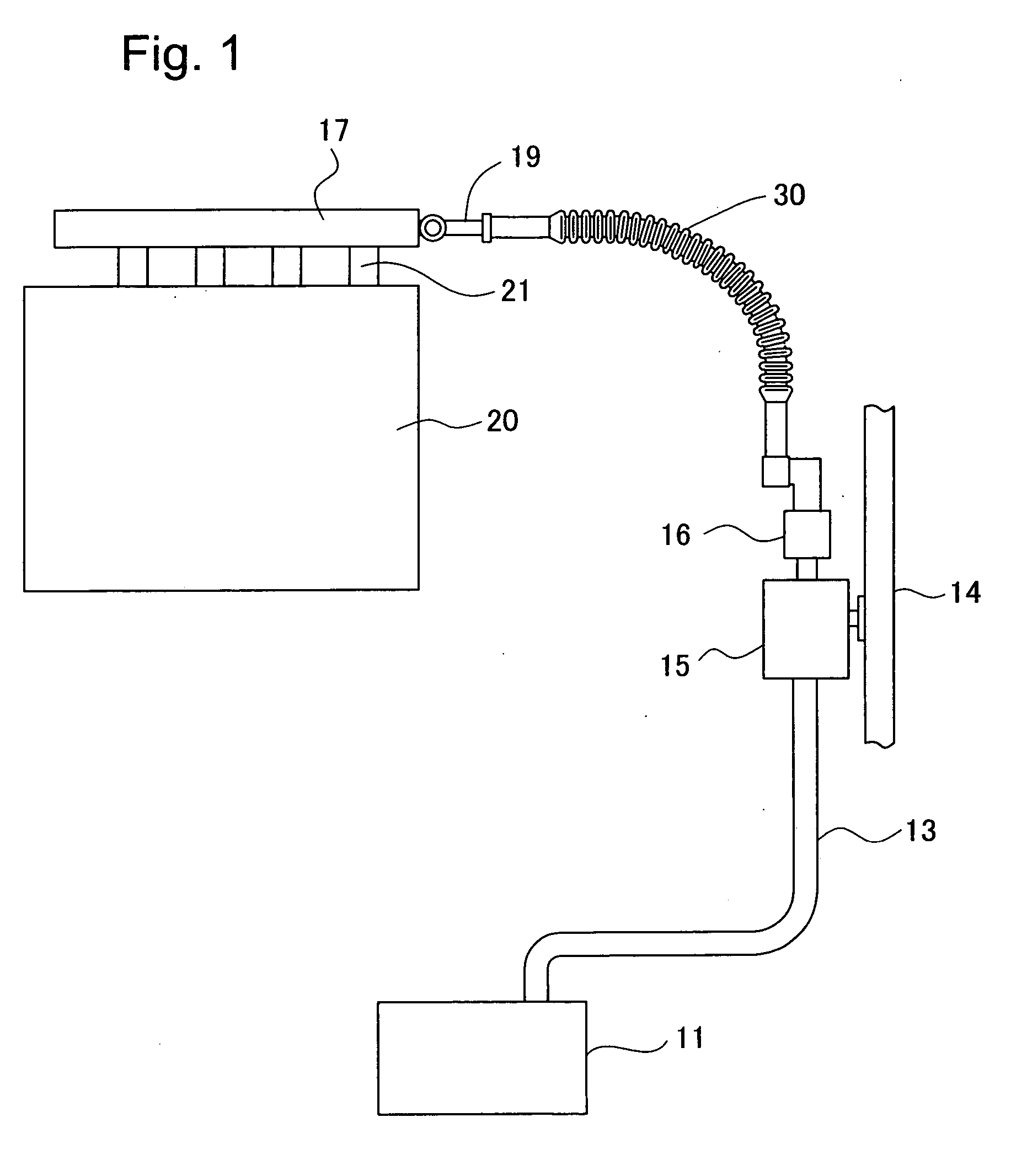
[0019]FIG. 1 is a schematic structural diagram of an automobile fuel feed system using a resin tube according to an embodiment of the invention. In FIG. 1, a metal fuel pipe 13 is connected through a fuel pump (not shown) in an automobile fuel tank 11. The fuel pipe 13 is connected to a filter 15 fixed to a dash board 14 behind the engine compartment. The corrugated tube (resin tube) 30 is connected by a quick connector 16 to an outlet of the filter 15. The corrugated tube 30 is drawn into the engine room and connected to a fuel injection valve 21 of an engine 20 by being connected to a cap 19 of a delivery pipe 17. In the fuel feed system, when fuel is pumped up from the fuel tank 11 by the fuel pump, the fuel is pumped under pressure into the corrugated tube 30 through the fuel pipe 13 and filter 15, and is injected into the engine 20 through opening and closing of the fuel injection valve 21. Fuel thus flows through the corrugated tube 30 upon changes in the pressure associated w...


PUM


Abstract

A corrugated tube 30 has corrugated sections 33 in which a plurality of peaks 33a and valleys 33b are alternately formed. The ratio Wb/Wa of the peak longitudinal breadth Wa and the valley longitudinal breadth Wb, with reference to a base line BL established at a position midway in the height direction between the peaks 33a and valleys 33b, is 1.2 to 2.0. The valley 33b floor is formed as a straight portion 33c formed to virtually the same outside diameter along the longitudinal direction of the corrugated tube 30. The corrugated tube 30 stretches less under fluid pressure and has less bending rigidity, improving a better disposition.

Description

[0001] This application claims the benefit of and priority from Japanese Application No. 2005-52578 filed Feb. 28, 2005, the content of which is incorporated herein by reference. BACKGROUND OF THE INVENTION [0002] 1. Field of the Invention [0003] The invention relates to a resin tube having a connecting section and a corrugated section formed alternate parts of peaks and valleys. [0004] 2. Description of the Related Art [0005] A conventional resin tube with a corrugated section is described in JP-A 2000-2376, which has been used as a tube employed to supply automobile gas. In addition to basic needs such as fuel pressure resistance and shock absorption, flexibility is required for better disposition in automobile engine compartments. However, when the resin tube is made more flexible, the corrugated section stretches and become considerably bent, meaning into contact with or interfering with peripheral parts. Efforts to overcome such problems by adjusting the thickness of the resin ...

Claims


Application Information

Patent Timeline
Patent Type & Authority Applications(United States)
IPC IPC(8): F16L11/00
CPCF16L11/11F16L2011/047
Inventor MORI, NAOKI
Owner TOYODA GOSEI CO LTD
Why Eureka
Try Eureka