Plasma display apparatus

Inactive Publication Date: 2006-09-28
SAMSUNG SDI CO LTD
View PDF12 Cites 9 Cited by
  • Summary
  • Abstract
  • Description
  • Claims
  • Application Information

AI Technical Summary

Benefits of technology

[0010] It is therefore an object of the present invention t

Problems solved by technology

Displaying the image on a plasma display apparatus leads to the generation of a large amount of heat.
Such heat degrades the display performance of the PDP and results in a degradation in the reliability of the circuit units when the plasma display apparatus is driven for a long time.
However, the heat dissipation unit may be formed of a material has a high thermal conductivity but releases debris.
In addition, the conductive debris contaminates the circu

Method used


Image

  • Plasma display apparatus
  • Plasma display apparatus
  • Plasma display apparatus

Examples


first embodiment

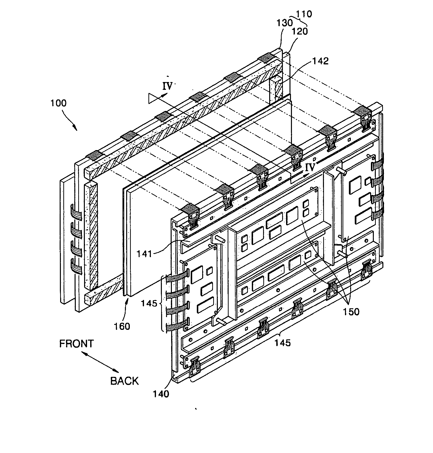
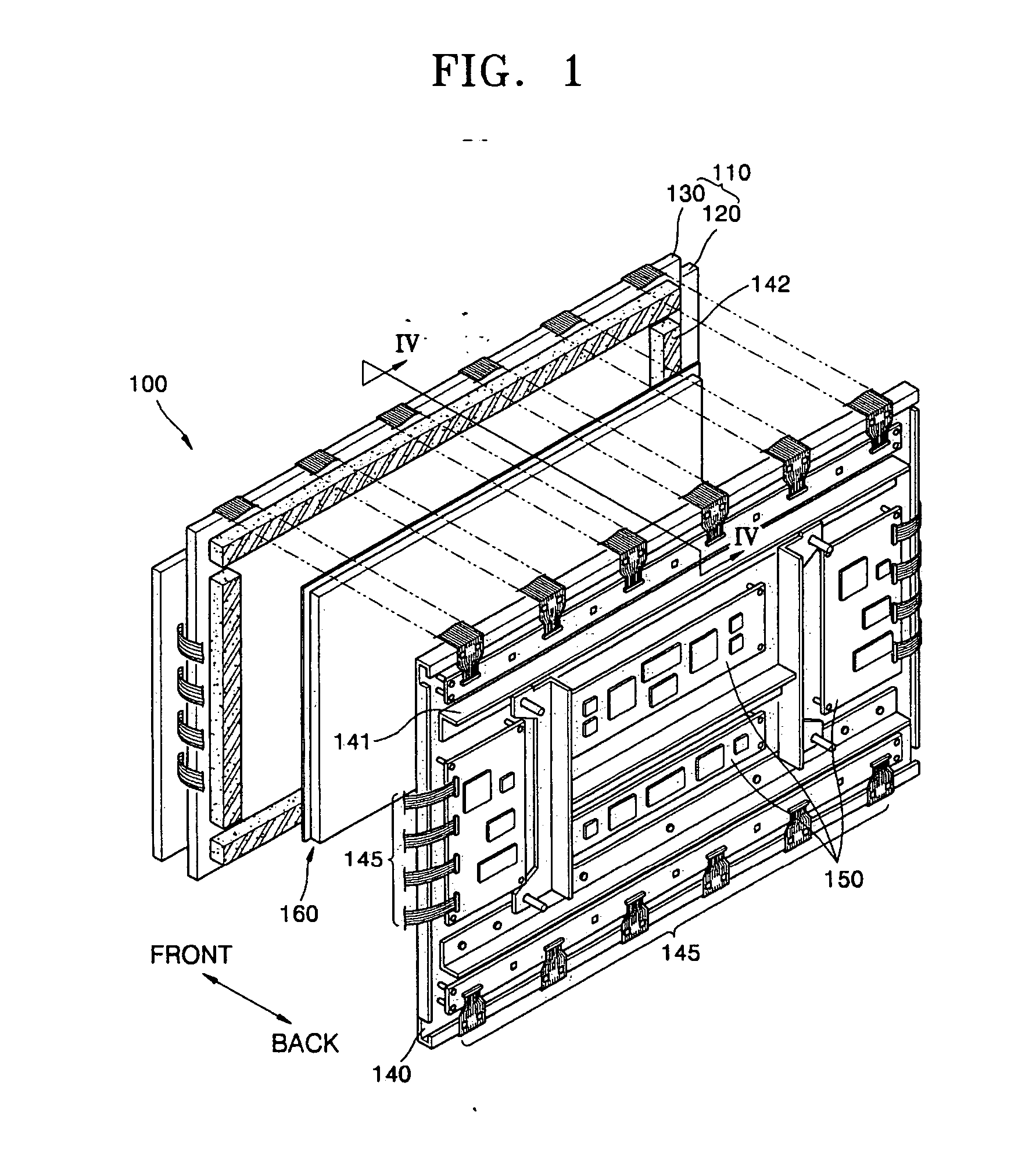
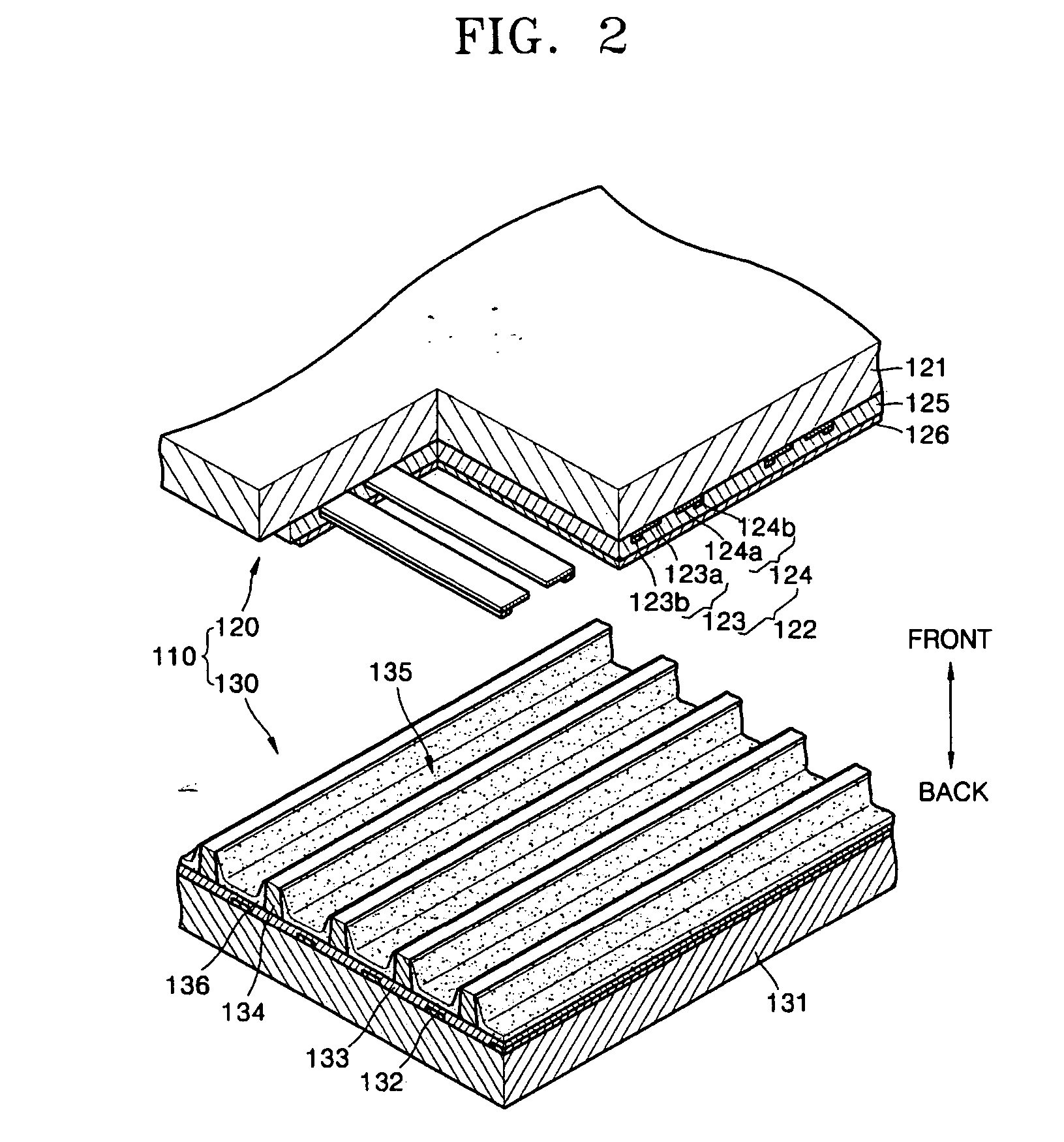
[0027] Referring now to FIG. 1, FIG. 1 illustrates a plasma display apparatus 100 according to the present invention. The plasma display apparatus 100 of FIG. 1 includes a plasma display panel (PDP) 110, a chassis base 140, and circuit units 150. The PDP 110 can be any of various types of PDPs that display images using a gas discharge phenomenon. For example, a surface-discharge three-electrode alternating current (AC) PDP as illustrated in FIG. 2 can be used as the PDP 110.

[0028] Turning now to FIG. 2, the PDP 110 of FIG. 2 includes a front panel 120 and a rear panel 130 facing the front panel 120. The front panel 120 includes a front substrate 121 and sustain electrode pairs 122 formed on a rear surface of the front substrate 121. The sustain electrode pairs 122 include an X electrode 123 and a Y electrode 124. A front dielectric layer 125 covers the sustain electrode pairs 122, and a protective layer 126 is formed on the rear surface of the dielectric layer 125 to cover the diele...

second embodiment

[0044] Turning now to FIG. 6, FIG. 6 is a cross-sectional view of a plasma display apparatus 200 according to the present invention. The plasma display apparatus 200 of FIG. 6 includes a PDP 210 having a front panel 220 and a rear panel 230, a chassis base 240, and a circuit unit 250. As illustrated in FIG. 6, adhesive members 242 and a heat dissipation unit 260 are disposed between the PDP 210 and the chassis base 240. Reinforcing members 241 are installed on the chassis base 240. As illustrated in FIG. 6, the heat dissipation unit 260 can be spaced apart from the chassis base 240 by space 270.

[0045] Referring to FIG. 6, the heat dissipation unit 260 can include a first heat dissipation element 261, an adhesive layer 262 coated on the first heat dissipation element 261, and a second heat dissipation element 263, which is a thin sheet contacting a surface of the adhesive layer 262. Second heat dissipation element 263 is attached to an opposite side of adhesive layer 262 than the sid...


PUM


Abstract

A plasma display apparatus that includes a plasma display panel adapted to display an image, a chassis base arranged at a rear of the plasma display panel, a circuit unit arranged on the chassis base and adapted to drive the plasma display panel and a heat dissipation unit arranged between the plasma display panel and the chassis base, the heat dissipation unit comprising a first heat dissipation element comprised of a material that produces debris, a first heat dissipation element arranged parallel to both the plasma display panel and the chassis base and adapted to dissipate heat generated by the plasma display panel and a second heat dissipation element covering at least a portion of the first heat dissipation element and being adapted to prevent debris from being released from the first heat dissipation element.

Description

CLAIM OF PRIORITY [0001] This application makes reference to, incorporates the same herein, and claims all benefits accruing under 35 U.S.C. § 119 from an application for PLASMA DISPLAY APPARATUS earlier filed in the Korean Intellectual Property Office on 23 Mar. 2005 and there duly assigned Serial No. No. 10-2005-002. BACKGROUND OF THE INVENTION [0002] 1. Field of the Invention [0003] A plasma display apparatus having a heat dissipation unit that has an improved structure and that dissipates heat generated by a plasma display panel. [0004] 2. Description of the Related Art [0005] Typically, a plasma display apparatus is a flat display apparatus that displays an image using a gas discharge phenomenon. The plasma display apparatus is superior in various display characteristics, such as a display capacity, a luminance, a contrast, image retention, and viewing angle. The plasma display apparatus can be made to have a large screen size while being thin. As a result, the plasma display a...

Claims


Application Information

Patent Timeline
IPC IPC(8): H01J17/49H05K7/20G09F9/00
CPCH01J11/12H01J2211/66H05K7/20963A01B1/022A01B1/20A01C5/02A01D1/04
Inventor JEONG, KWANG-JIN
Owner SAMSUNG SDI CO LTD
Why Eureka
Try Eureka