Image forming device

a technology of forming device and image, which is applied in the direction of power drive mechanism, printing, instruments, etc., can solve the problems of compromising printing accuracy, etc., and achieve the effect of convenient positioning and quick positioning

Inactive Publication Date: 2006-09-28
FUNAI ELECTRIC CO LTD
View PDF3 Cites 7 Cited by
  • Summary
  • Abstract
  • Description
  • Claims
  • Application Information

AI Technical Summary

Benefits of technology

[0017] The present invention provides an image forming device configured such that the thermal head unit can be readily and easily positioned with respect to the platen roller, without having to compromise the print quality.

Problems solved by technology

As a result, the printing accuracy tends to be compromised.

Method used


Image

  • Image forming device
  • Image forming device
  • Image forming device

Examples


first embodiment

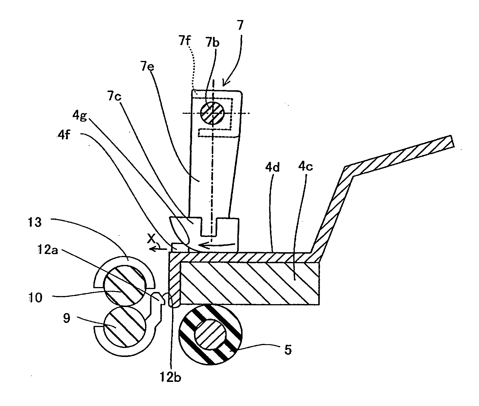
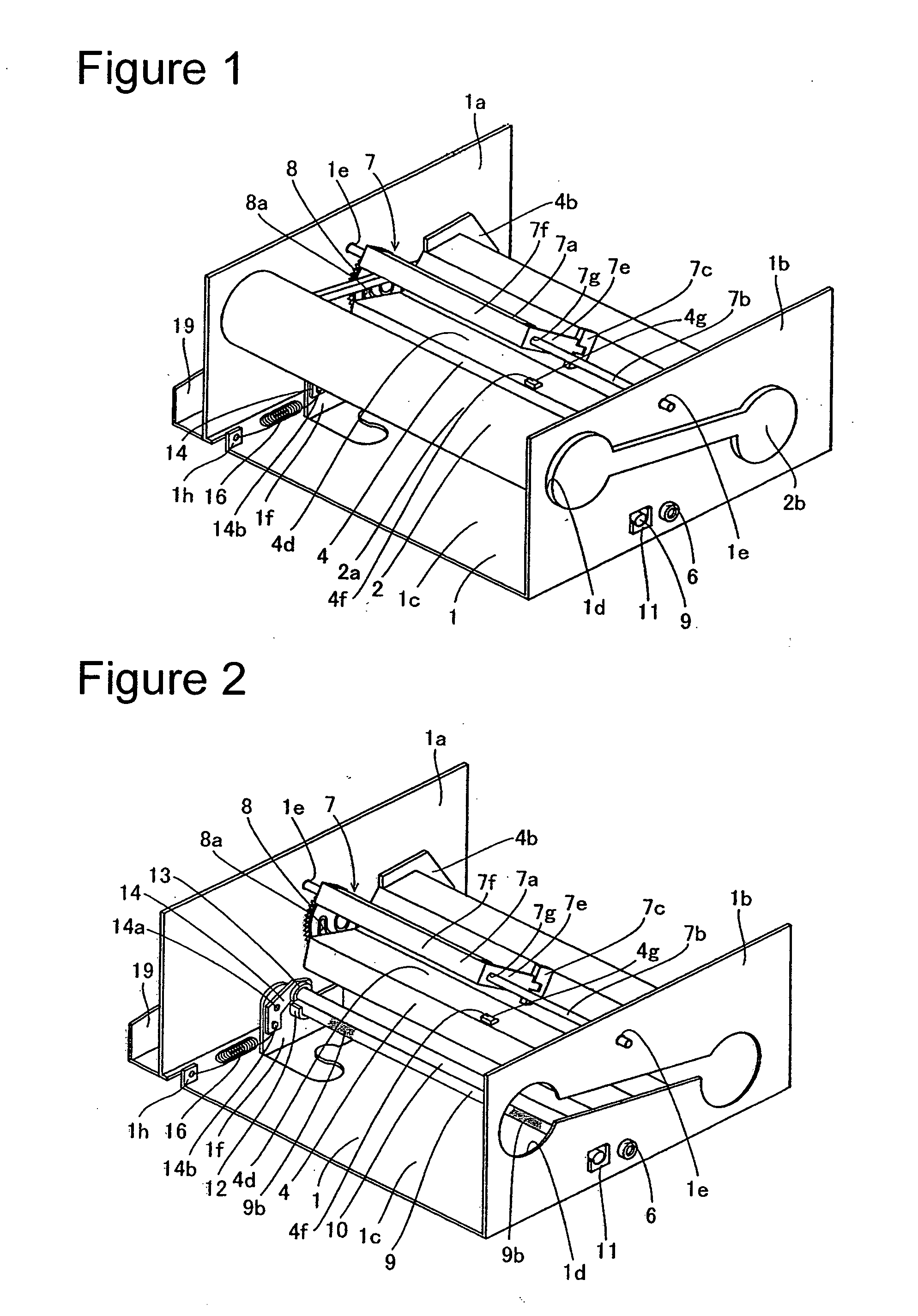
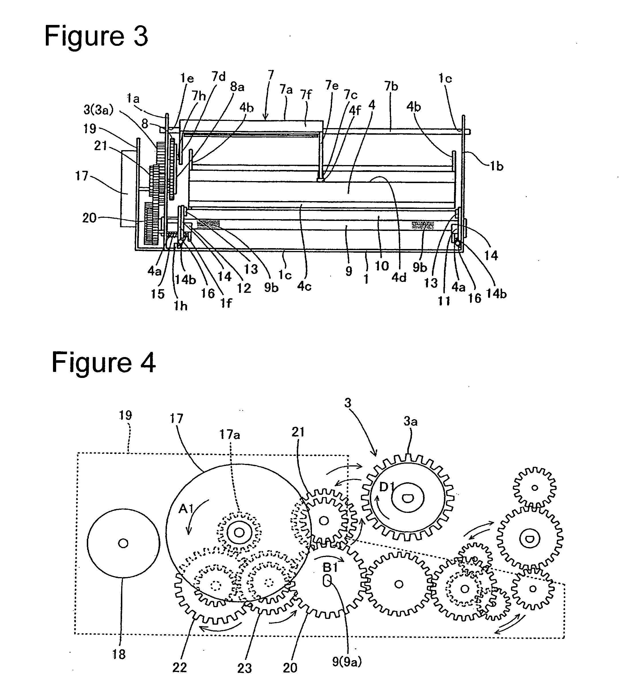
[0054]FIG. 1 is a perspective view showing the overall structure of a thermal transfer printer in accordance with a first embodiment of the present invention. FIGS. 2 to 14 illustrate the constituent features of a thermal transfer printer in accordance with the first embodiment of the present invention in more detail. The structure of the thermal transfer printer in accordance with the first embodiment of the present invention will now be described with reference to FIGS. 1 to 14. This embodiment illustrates a case in which the present invention is applied to a thermal transfer printer, which is one example of an image forming device.

[0055] As shown in FIGS. 1 to 4 and FIG. 10, the thermal transfer printer in accordance with the first embodiment of the present invention includes: a metal chassis 1, an ink ribbon cartridge 2, a take-up reel 3 (see FIG. 4), a thermal head unit 4 for executing printing, a platen roller 5 (see FIG. 10) arranged opposite the thermal head unit 4, platen ...

second embodiment

[0082]FIG. 15 is a perspective view showing the overall structure of a thermal transfer printer in accordance with a second embodiment of the present invention. FIG. 16 is a partial perspective view of the thermal head unit of the thermal transfer printer in accordance with the second embodiment shown in FIG. 15. FIG. 17 is a schematic side view showing the thermal transfer printer in a pressed condition. FIG. 22 is a partial perspective view of the thermal head unit of the thermal transfer printer in accordance with an alternative configuration of the second embodiment. The second embodiment will now be explained with reference to FIGS. 15 to 17 and 22.

[0083] Unlike the first embodiment, the second embodiment has a projecting part that is provided on the heat sink of the thermal head unit and configured to contact the feed roller bearing. The structures of components of the thermal transfer printer of the second embodiment other than the thermal head unit, the feed roller, the pre...


PUM


Abstract

The image forming device includes a chassis; a thermal head unit pivotably supported by the chassis for executing printing; a platen roller supported by the chassis opposite the thermal head unit; a pressing member that is pivotably supported by the chassis and configured to press the thermal head unit against the platen roller by pushing against a top portion of the thermal head unit; a protruding part that is provided on the top portion of the thermal head unit and configured to engage the pressing member in a horizontal direction as the pressing member is pivoted to press the thermal head unit against the platen roller; and a positioning member configured to engage the thermal head unit as the thermal head unit is pushed in the horizontal direction due to the engagement of the protruding part with the pressing member in the horizontal direction.

Description

BACKGROUND OF THE INVENTION [0001] 1. Field of the Invention [0002] The present invention relates to an image forming device. More specifically, the present invention relates to an image forming device equipped with a member that presses a thermal head unit. [0003] 2. Background Information [0004] Various structures of thermal transfer printers and other image forming devices have been proposed which include a member for pushing a thermal head or print head. [0005] An image forming device is a known example of the thermal transfer printer. FIG. 18 is a perspective view showing the overall structure of a known example of a thermal transfer printer. FIGS. 19 to 21 illustrate the thermal transfer printer shown in FIG. 18 in more detail. This thermal transfer printer will now be described with reference to FIGS. 18 to 21. [0006] As shown in FIGS. 18 to 21, this thermal transfer printer includes a metal chassis 101, an ink ribbon cartridge 102, a take-up reel 103 (see FIGS. 19 and 20), a...

Claims


Application Information

Patent Timeline
Patent Type & Authority Applications(United States)
IPC IPC(8): B41J25/304B41J2/32
CPCB41J2/32B41J25/304B41J2202/31
Inventor SAWAI, KUNIO
Owner FUNAI ELECTRIC CO LTD
Why Eureka
Try Eureka