Fluid bed granulation process and apparatus

a technology of granulation process and fluid bed, which is applied in the direction of granulation by powder suspension, coating, pill delivery, etc., can solve the problems of unsatisfactory cost-effectiveness, unsatisfactory granulation effect, and unsatisfactory granulation effect, so as to achieve the effect of simple operation

Active Publication Date: 2007-01-25
CASALE SA
View PDF39 Cites 2 Cited by
  • Summary
  • Abstract
  • Description
  • Claims
  • Application Information

AI Technical Summary

Benefits of technology

[0021] The technical problem underlying the present invention is that of devising and providing a granulation process for obtaining finished granules of a predetermined substance in a granulation fluid bed of the so-called vertical growth type, wherein said bed is formed and maintained by a respective flow of fluidification air, comprising a transfer phase by falling of said finished granules in a pressurized space below said granulation bed and a recovery phase of said granules from said pressurized space, wherein the recovery of the finished granules takes place in a way that is simple to carry out, reliable and which does not require a burdensome and difficult maintenance, and at the same time with functional characteristics such as to safeguard the grain size of said finished granules, and the integrity of the monodispersed finished granules thus produced.

Problems solved by technology

In particular, in such a process, as the granulation progresses the granules increase in size and weight, until the flow of fluidification air which crosses the aforementioned slits is no longer able to support them any further.
But the use of such extracting systems would predictably involve some drawbacks that aren't totally acceptable in the cost-effectiveness of the granulation process intended to be actuated.
Indeed, a continuous mechanical extraction, from a pressurized space, like the one considered above, to be able to ensure limited or at least controlled losses of air in the granule-collection space and therefore to ensure a satisfactory seal between extractor and respective granule-discharge opening, is constructively very complex to realize and requires burdensome and difficult maintenance operations.
A further drawback, linked to the mechanical manipulation of the finished and classified granules, consists of the danger of said granules undergoing a sort of grinding or crushing, with the formation of powders and with an even substantial reduction in yield of the entire productive cycle.

Method used


Image

  • Fluid bed granulation process and apparatus
  • Fluid bed granulation process and apparatus
  • Fluid bed granulation process and apparatus

Examples


Embodiment Construction

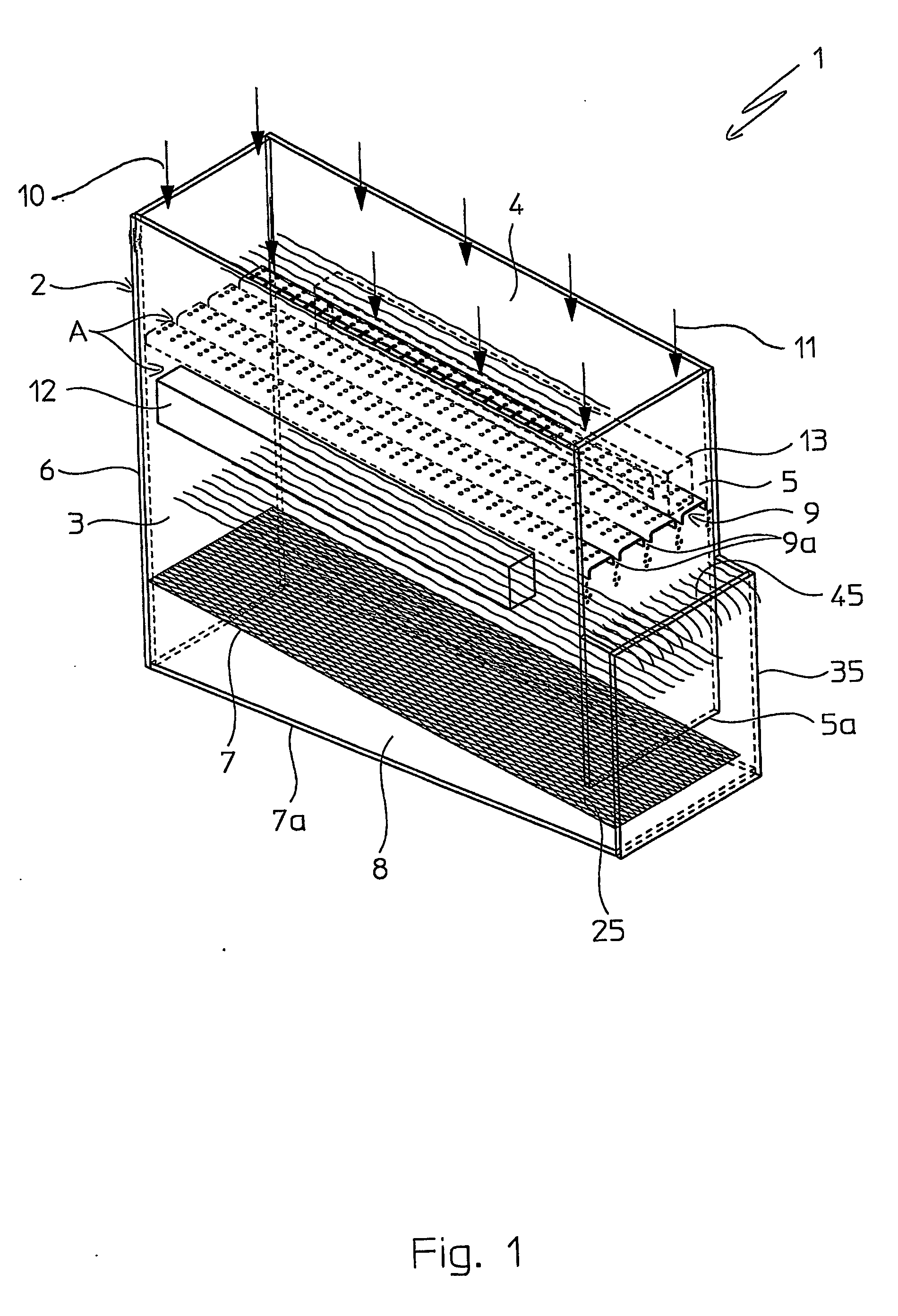
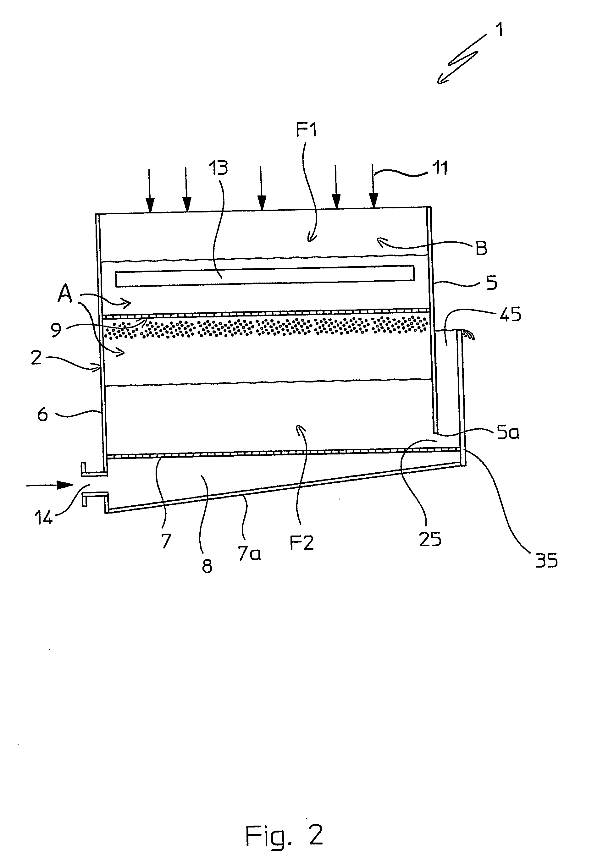
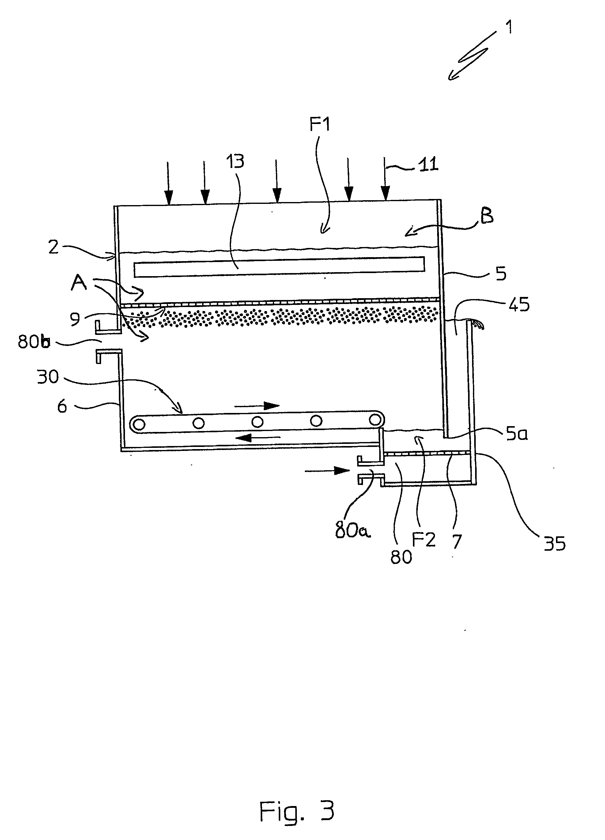
[0029] With reference to the aforementioned figures, an apparatus for carrying out the process of the present invention is schematically indicated with 1.

[0030] Such an apparatus comprises a self-supporting structure 2, substantially in the shape of a parallelepiped container, which defines a space A inside it, in which two fluid beds F1 and F2 are intended to be realized, as can be seen more clearly in the rest of the description.

[0031] Said container structure 2 (which hereafter shall simply be called: container 2), has long side walls 3, 4, short front 5 and rear 6 walls; and, at the bottom, it is equipped with a double base plate, 7, 7a, upper and lower respectively.

[0032] In accordance with a characteristic of the present invention, the front wall 5, of said container 2, has the bottom side 5a, spaced from the base plate 7, of said double base plate, with which it thus defines a passage (or port) 25, which places the space A in communication with the outside of said containe...


PUM

PropertyMeasurementUnit
lengthaaaaaaaaaa
sizeaaaaaaaaaa
grain sizeaaaaaaaaaa

Abstract

A process for obtaining finished granules of a predetermined substance in a granulation fluid bed (F1) of the so-called vertical growth type, the bed being formed and maintained by a respective flow of fluidification air, comprises a transfer phase by falling of the finished granules in a pressurized space below the granulation bed and a recovery phase of the finished granules from the pressurized space.

Description

FIELD OF APPLICATION [0001] In its most general aspect, the present invention refers to a fluid bed granulation process for obtaining finished granules of a predetermined substance, comprising a recovery phase of said finished granules from the granulation fluid bed. [0002] In the rest of the description and in the subsequent claims, with the terms: “finished granules” we mean granules of the predetermined substance of a predetermined size or, in other words, having predetermined grain size. [0003] The process of the present invention is particularly, but not exclusively recommended for the fluid bed granulation of substances like, for example, urea, ammonium nitrate, ammonium chloride and similar substances susceptible to being granulated. [0004] The invention also refers to a granulation apparatus, used to carry out the aforementioned process. PRIOR ART [0005] As is known, in a fluid bed granulation process, the obtainment of granules of a predetermined substance takes place throu...

Claims


Application Information

Patent Timeline
Patent Type & Authority Applications(United States)
IPC IPC(8): A61K9/28A61K9/50B01J2/16
CPCB01J2/16
Inventor BEDETTI, GIANFRANCO
Owner CASALE SA
Why Eureka
Try Eureka