Disk array apparatus

a technology of array apparatus and disk drive, which is applied in the direction of electric apparatus casing/cabinet/drawer, record information storage, instruments, etc., can solve the problems of insufficient cooling of the inability to mount the array of disk drives, etc., and achieve the effect of sufficient cooling

Inactive Publication Date: 2007-03-08
HITACHI LTD
View PDF12 Cites 133 Cited by
  • Summary
  • Abstract
  • Description
  • Claims
  • Application Information

AI Technical Summary

Benefits of technology

[0014] According to this invention, it is possible to provide a disk array apparatus that can car

Problems solved by technology

However, a conventional disk array apparatus is configured in such a way that disk drives are installed only two-dimensionally.
Accordingly, the nu

Method used


Image

  • Disk array apparatus
  • Disk array apparatus
  • Disk array apparatus

Examples


Embodiment Construction

[0032] Preferred embodiments of this invention will be described below in detail with reference to the attached drawings.

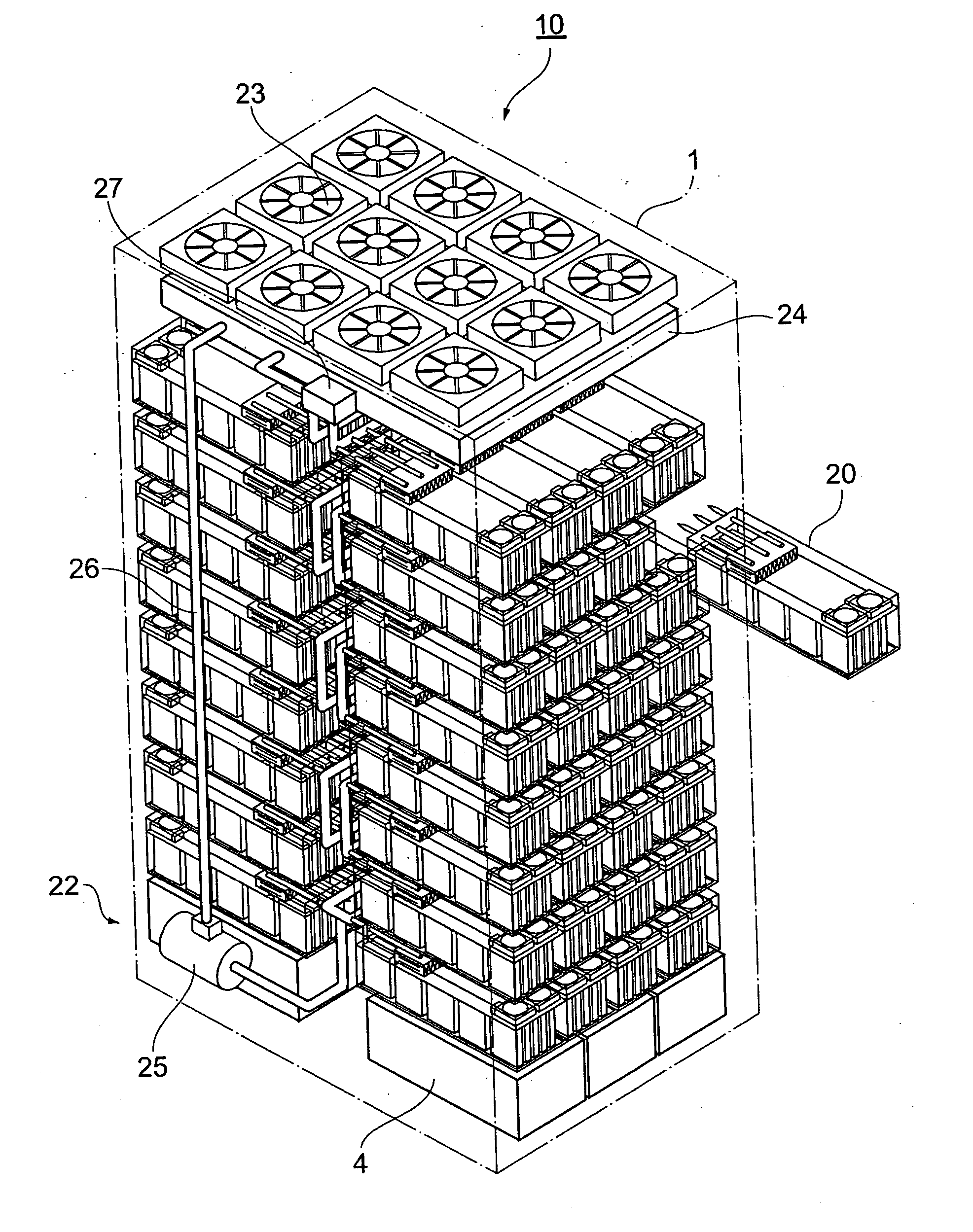
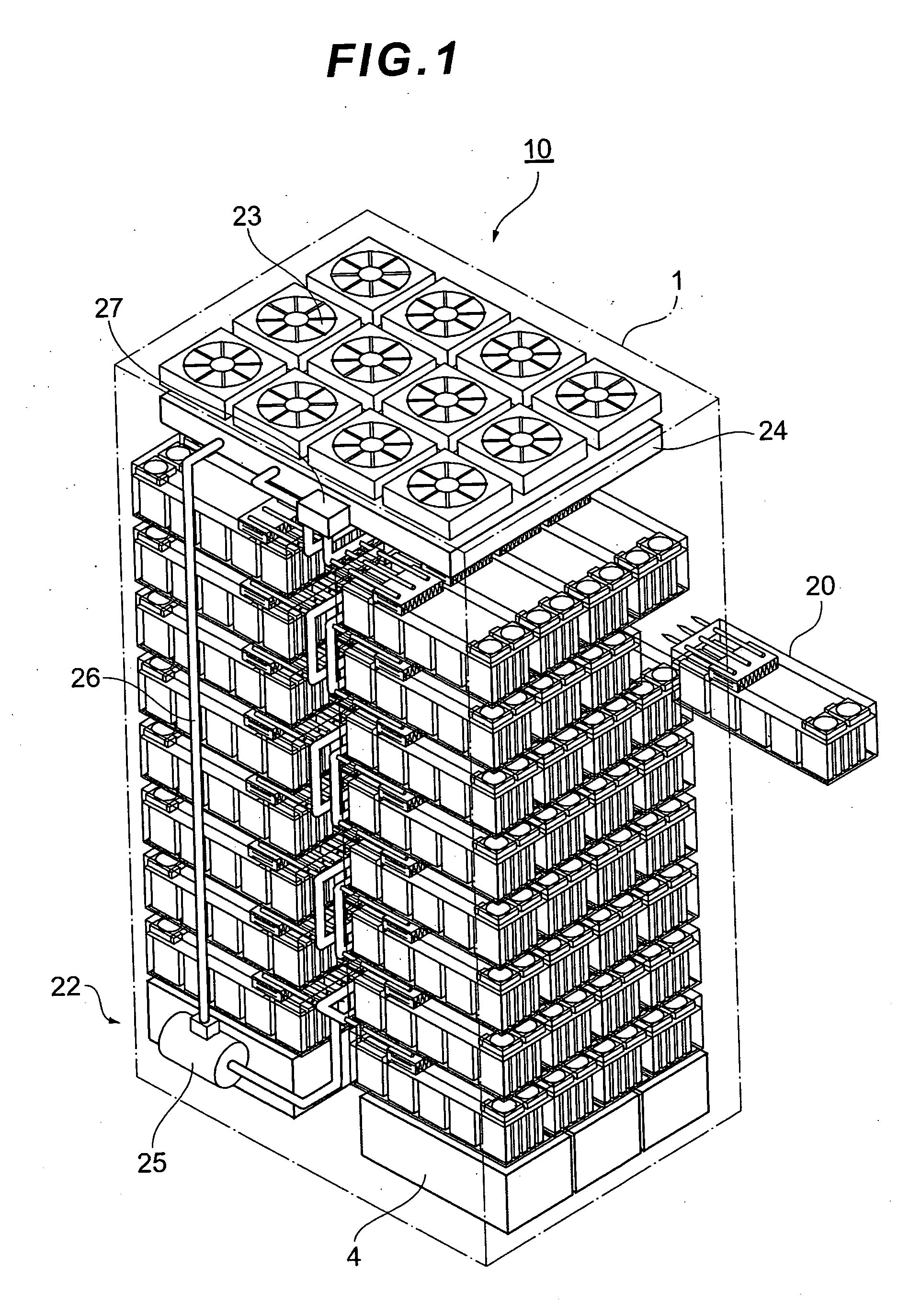
[0033]FIG. 1 shows the external view of a disk array apparatus 10 according to an embodiment of this invention. The main components of the disk array apparatus 10 are a rack-shaped basic frame 1 and a plurality of disk boxes 20.

[0034] The basic frame 1 forms the basic skeleton of the disk array apparatus 10 and has a frame structure that can mount a plurality of disk boxes 20 on both its front and back sides. The disk box 20 is a box used to accommodate a plurality of disk drives and has a box structure that allows the disk box 20 to be freely inserted into or pulled out of the basic frame 1 depth-wise.

[0035] A power supply unit 4 for supplying electric power to the disk boxes 20 is placed at the bottom of the basic frame 1. The power supply unit 4 contains an AC power supply and an AC / DC converter. By locating the heavy-weight power supply unit 4 at the bottom...


PUM


Abstract

A disk array apparatus including a rack-shaped basic frame, and a plurality of disk boxes that can be inserted into and pulled out of the basic frame depth-wise. Each disk box has: disk drive connectors for connecting a plurality of disk drives arranged in a matrix on a platter substrate, which is the bottom face of the disk box, roughly parallel to the depth direction of the basic frame; and a cooling module for cooling the disk drives. The disk box is a hermetically sealed structure.

Description

CROSS-REFERENCES TO RELATED APPLICATIONS [0001] This application relates to and claims priority from Japanese Patent Application No. 2005-254644, filed on Sep. 2, 2005, the entire disclosure of which is incorporated herein by reference. BACKGROUND OF THE INVENTION [0002] The present invention relates to a disk array apparatus for mounting a plurality of disk drives. [0003] A disk array apparatus that stores large-volume data carries a multiplicity of disk drives and provides storage areas configured, for example, in a RAID (Redundant Arrays of Independent / Inexpensive Disks) system, to a host system. A conventional disk array apparatus is configured in such a way that a plurality of disk boxes is mounted in a rack-shaped basic frame. Each disk box contains a plurality of disk drives. The disk drives are placed on a back board formed on the back face of the disk box and thereby electrically connected to a disk controller and a power supply unit. [0004] As the high-density mounting of ...

Claims


Application Information

Patent Timeline
IPC IPC(8): G06F1/20
CPCG11B33/022G11B33/144G11B33/1406G11B33/12
Inventor FUKUDA, HIROSHIMATSUSHIMA, HITOSHI
Owner HITACHI LTD
Why Eureka
Try Eureka