
PC camera direction positioning structure concealed in filling toy

a technology of positioning structure and camera, which is applied in the direction of camera body details, instruments, printing, etc., can solve the problems of inconvenient use, inconvenient assembly and operation, and inconvenient us

Inactive Publication Date: 2007-03-22
LIANG HUI HU
View PDF6 Cites 5 Cited by
  • Summary
  • Abstract
  • Description
  • Claims
  • Application Information

AI Technical Summary

Benefits of technology

[0008] (3) To clamp onto monitor of computer with clamping holder or clamping lock may produce clamp force to monitor, thereby, it is easy to damage appearance of structure, and to cause inconvenient use and impact on the aesthetic feeling of appearance.
[0011] b. The overall turning of plastic connector can let its structure complete best multi-directional seizing and positioning in accordance with shape and angle of application area, therefore, it is applicable in any place and can provide stable positioning and practical efficiency.
[0012] c. The assembling structure of this invention may not make any damage to the clamping position (such as monitor of computer or tabletop), but also provide a visual aesthetic feeling to user, so that application of PC camera may be more interesting.

Problems solved by technology

(1) Above described PC camera, no matter positioned by clamping holder or clamping lock, which often utilize clamping mouth in certain clamping gap to clamp or lock up directly, however, it is often inconvenient to assemble and operate due to the fixed gap of clamping mouth, therefore, such frame is not practical.
(3) To clamp onto monitor of computer with clamping holder or clamping lock may produce clamp force to monitor, thereby, it is easy to damage appearance of structure, and to cause inconvenient use and impact on the aesthetic feeling of appearance.

Method used


Image

  • PC camera direction positioning structure concealed in filling toy
  • PC camera direction positioning structure concealed in filling toy
  • PC camera direction positioning structure concealed in filling toy

Examples


Embodiment Construction

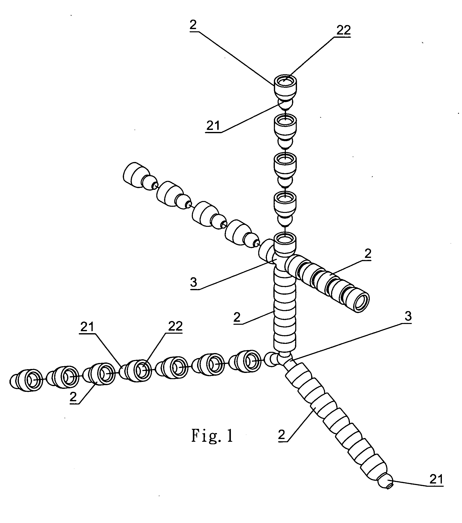
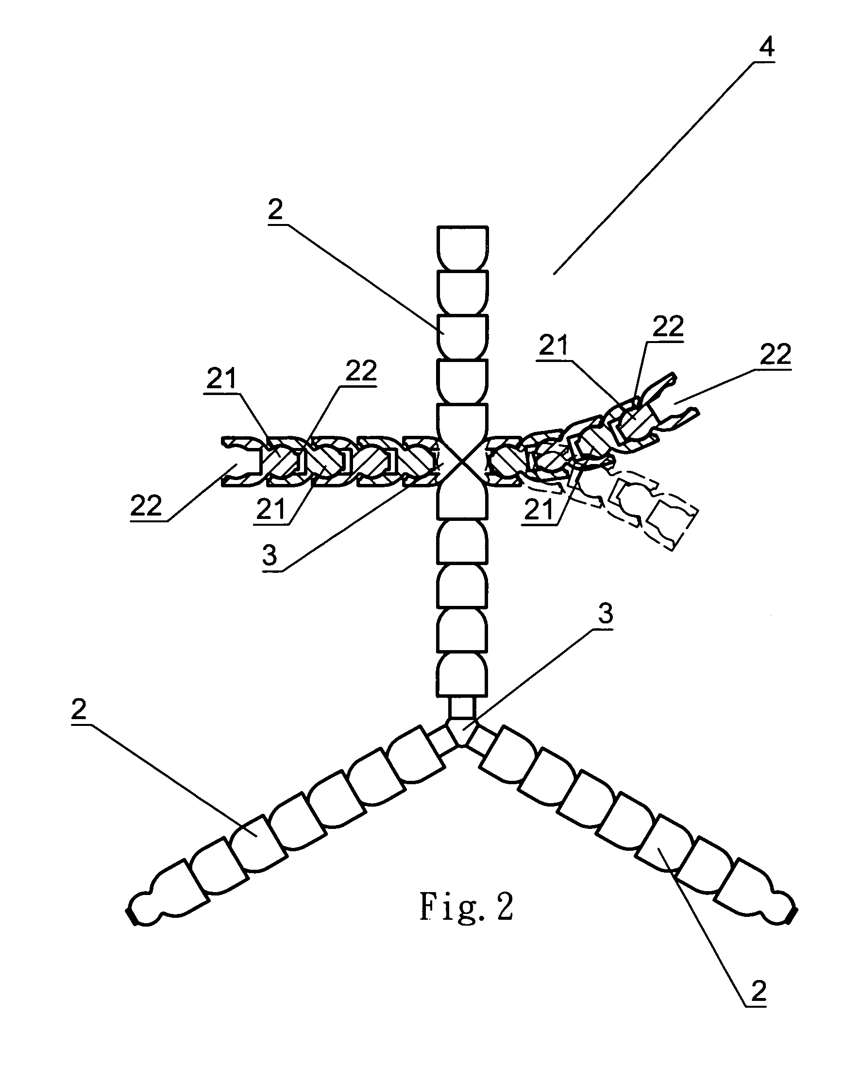
[0018] First of all, please refer to FIG. 1 and FIG. 2, this invention is to put the plastic sectional parts together in order, of which one end is ball-shaped body 21 and another end is ball groove 21, ball-shaped body 21 is embedded into ball groove 22, and to rabbet three-way or four-way joints 3 at turning point so as to make a man-shaped plastic connector 4 (refer to FIG. 2 for detail).

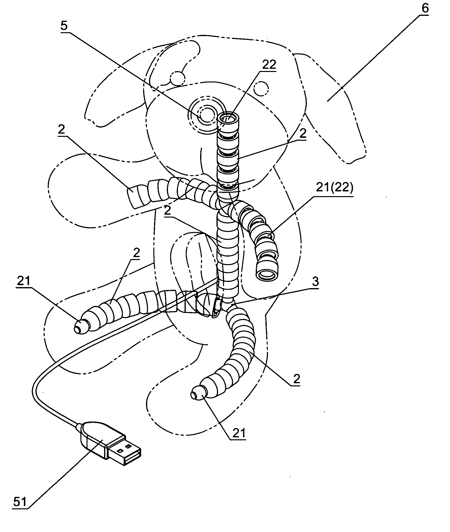
[0019] Secondly, please refer to FIG. 3, FIG. 4 and FIG. 5, plastic connector 4 of this invention can be wrapped into filling toy 6 assembled PC camera 5 and become the support frame concealed in filling toy 6 (refer to FIG. 3), PC camera concealed in filling toy 6 is connected to the control system of host computer with connection plug 51, so that it can take instant shooting while communicating (refer to FIG. 4 for structure); Based on suitable adjustment, the filling toy can sit or directly grovel and grasp any position of monitor 7, lens of PC camera fixed at top head of filling toy 6 can sh...


PUM


Abstract

A PC camera direction positioning structure concealed in filling toy, which is to put plastic sectional parts together in order, of which one end is ball-shaped body and another end is ball groove, ball-shaped body is embedded into ball groove, and to rabbet three-way or four-way joints at turning point so as to make a man-shaped plastic connector; this connector is then wrapped into a filling toy assembled PC camera, the filling toy can sit or directly grovel and grasp any position of monitor based on suitable adjustment, lens of PC camera fixed at top head of filling toy can shoot at correct direction, therefore, this structure can further improve external appearance of PC camera that can take shooting in different modes and angles in practice.

Description

BACKGROUND OF THE INVENTION [0001] 1) Field of the Invention [0002] This invention relates to PC camera direction positioning structure concealed in filling toy, wherein plastic connector is put together with plastic sectional part and multi-way joint, which is wrapped in a filling toy assembled PC camera and lens fixed at its head, so that the filling toy can be positioned in any pose and provide web shooting in different directions and angles. [0003] 2) Description of the Prior Art [0004] As long as the improvement and change of technology in every passing day, Internet communication has been becoming an important commodity of modern people, application of computer is no longer to process files and receive & dispatch E-mail, you can directly make web communication, have video chat and hold video conference depending on shooting of PC camera and related computer software, which has been favored by individual or company because of its clear and convenient video effect, and also beca...

Claims


Application Information

Patent Timeline
Patent Type & Authority Applications(United States)
IPC IPC(8): G03B19/00G03B17/48G03B29/00
CPCG03B29/00
Inventor LIANG, HUI-HU
Owner LIANG HUI HU
Learn More