Procedure and device for linearizing the characteristic curve of a vibration signal transducer such as a microphone

a technology of vibration signal transducer and characteristic curve, which is applied in the direction of frequency response correction, instruments, electrophonic musical instruments, etc., can solve the problems of large feedback level, loud screech, and fluctuation of the whole signal, so as to eliminate the instability caused by feedback and fluctuations

Inactive Publication Date: 2007-04-12
PAKZAD SAMAD F
View PDF3 Cites 7 Cited by
  • Summary
  • Abstract
  • Description
  • Claims
  • Application Information

AI Technical Summary

Benefits of technology

[0017] The present invention overcomes these disadvantages by changing each characteristic curve into nearly a

Problems solved by technology

This phenomenon generates instability in the system and tends to cause signal fluctuations, especially at higher yield frequencies; the more that energy increases, the greater the level of feedback.
The new and returned signals are then reamplified, which, due to the non-linear nature of the elements making up the transfer chain, results in a fluctuation of the whole signal, which in turn results in a very loud screech that is characteristic of the Larsen effect.
All of these methods help reduce feedback, but the limitations that they impose often limit the system capabilities and reduce the expected quality.
Items such as portable wireless telephones (cell phones) or, to an even greater extent, hearing aids must be contained in the most compact structure possible, which is completely incompatible with the concept of keeping a large distance between the microphone and the speaker (or earpiece in t

Method used


Image

  • Procedure and device for linearizing the characteristic curve of a vibration signal transducer such as a microphone
  • Procedure and device for linearizing the characteristic curve of a vibration signal transducer such as a microphone
  • Procedure and device for linearizing the characteristic curve of a vibration signal transducer such as a microphone

Examples


Embodiment Construction

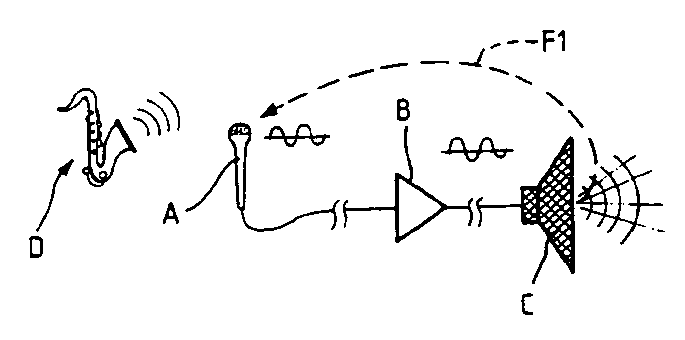
[0042]FIG. 1 illustrates a well-known configuration consisting of an input transducer, microphone A, amplification-transmission circuit B, and an output transducer, in this case speaker C. An “input” impedance adapter is typically installed at the input of circuit B and an “output” impedance adapter is installed at the output of circuit B. The sound produced by musical instrument D is picked up by microphone A, transformed into electrical signals to be sent to circuit B, amplified to a greater or lesser extent, and then sent to speaker C, which transforms the received electrical signals into sounds.

[0043] As shown, part of the sound transmitted by speaker C bounces off objects and surfaces in the surroundings and is picked up by microphone A, which is depicted by a simple arrow and dotted line F1. This sound is treated exactly like the main sound: i.e., it is transformed into electric signals, amplified and transmitted. If the feedback level is significant, this creates significant...


PUM


Abstract

A procedure and device for linearizing the characteristic curve of a vibration signal transducer such as a microphone that includes collecting signals, transmitting the signals, extracting information from the signals, dephasing such information by 180 degrees compared to the initial signals and taking the algebraic sum of the initial signals and dephased information.

Description

BACKGROUND OF THE INVENTION [0001] Vibration signals, such as sound signals, are transmitted between different points under many circumstances. Many of these require transcoding and / or amplification. For example, orchestras and musical groups play in public, and their sounds must be amplified for a group of listeners; telephones and radios transmit voices and music over long distances, the first via wires, the second via radio waves; hearing aids amplify sounds collected from the user's environment and deliver them to the eardrum or to said user's ear bone structures; television takes images collected using a video camera, transforms them into electronic signals and then recreates them on viewers' screens after decoding. [0002] In all instances, the signals are collected at the transmitting point, transformed into electronic signals, generally amplified, and then reconstituted at the reception point. [0003] The transducers that transform the mechanical vibrations into electronic sig...

Claims


Application Information

Patent Timeline
IPC IPC(8): G10H3/00
CPCH04R3/04H04R27/00
Inventor PAKZAD, SAMAD F.
Owner PAKZAD SAMAD F
Why Eureka
Try Eureka