Wing leading edge slat system

Inactive Publication Date: 2007-05-10
THE BOEING CO
View PDF12 Cites 83 Cited by
  • Summary
  • Abstract
  • Description
  • Claims
  • Application Information

AI Technical Summary

Benefits of technology

[0007] A mechanism for extending and supporting a high-lift device relative to an airfoil has a pair of support ribs coupled to the airfoil. A carrier track is pivotally coupled to the high-lift device and positioned between the pair of support ribs. The carrier track has a slot opening along a lower length thereof. A gear rack is coupled within the slot opening. A pinion gear is positioned between the support ribs and b

Problems solved by technology

Due to the limited stowage volume in the wing cross-section, designing actuation systems for moving and positioning the leading edge slats in the wing has been difficult.
These systems tend to take up a large amount of area in the wing cross-section.
The combination of

Method used


Image

  • Wing leading edge slat system
  • Wing leading edge slat system
  • Wing leading edge slat system

Examples


Embodiment Construction

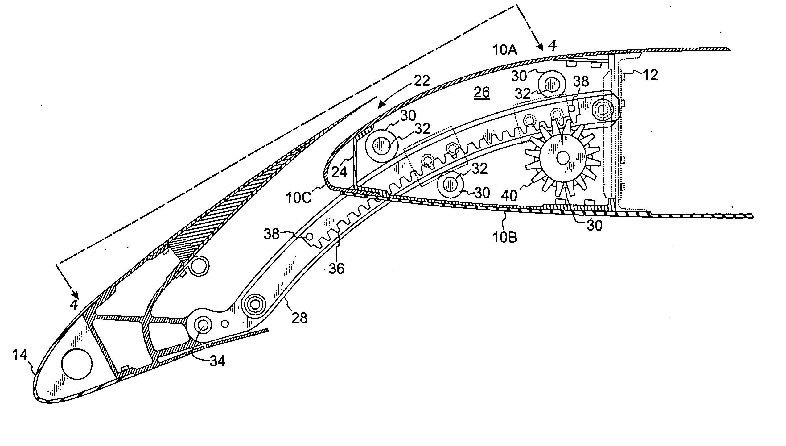
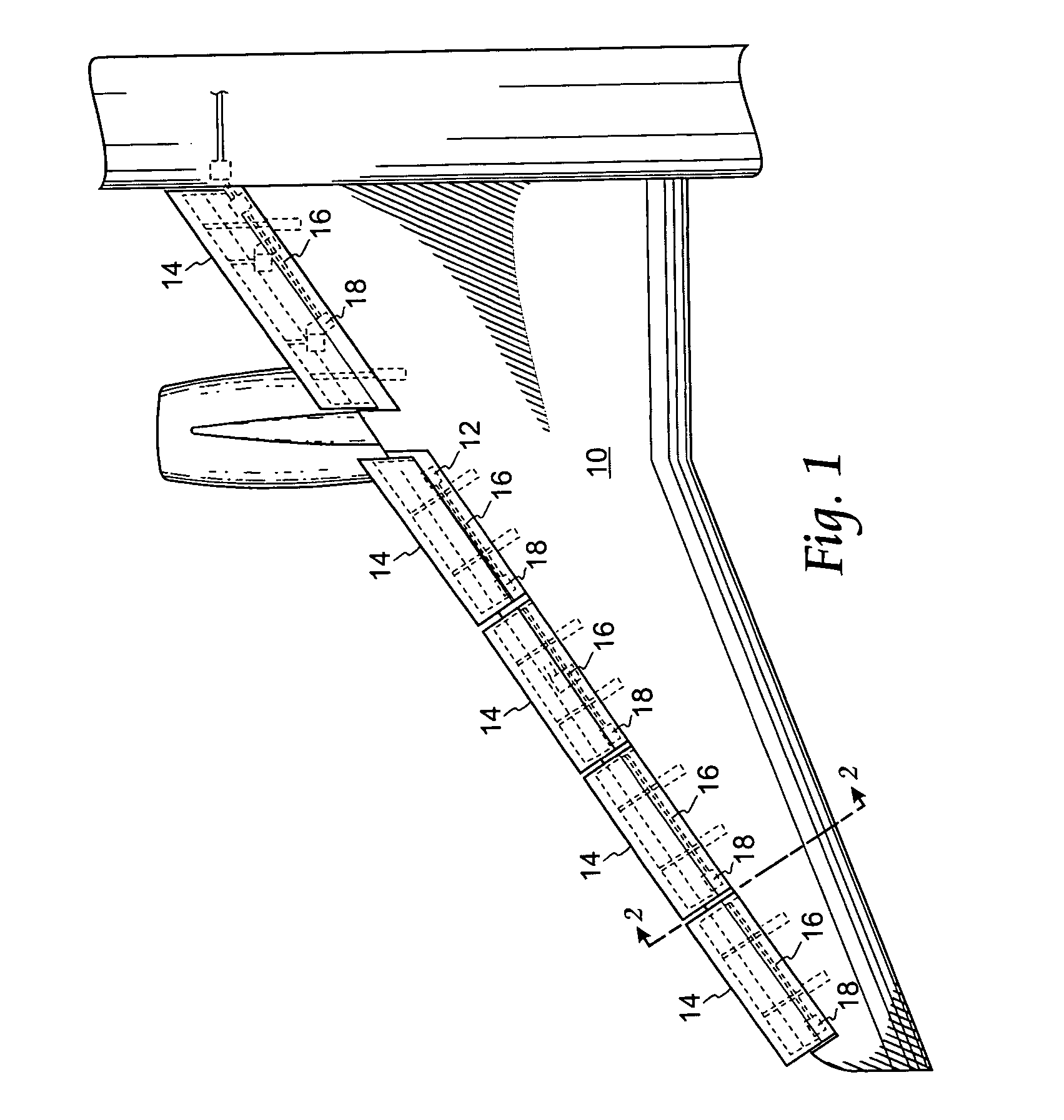
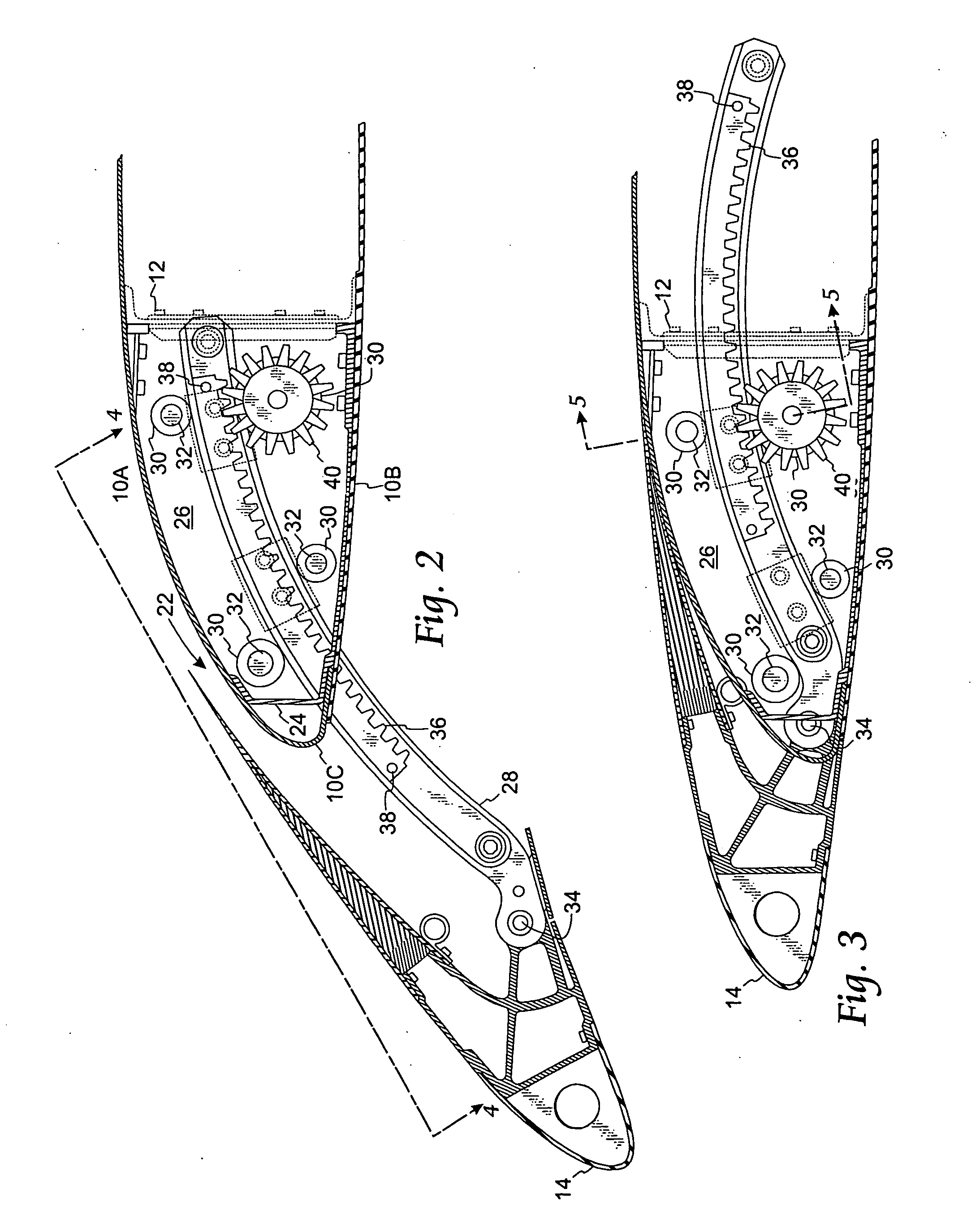
[0015] Referring to FIG. 1, a plan view of an outboard, leading edge section of an airplane wing 10 is shown. The wing 10 has a front wing spar 12 and a spanwise series of slat panels 14 along the leading edge of the wing 10. A power drive system is mounted spanwise along the front wing spar 12 for extending or retracting the slat panels 14 relative to a fixed wing leading edge. In accordance with one embodiment, the power drive system, which will be described in more detail below, comprises: a power drive unit (not shown) such as a hydraulic or electric drive motor for rotating a spanwise series of axially aligned shafts or torque tubes 16 (hereinafter shafts 16), at a relatively high speed. The shafts 16 operate the extension or retraction mechanism of the slat panels 14 through a speed reducer and torque converter unit hereinafter referred to a rotary actuator 18. Each of the rotary actuators 18 is mounted to a slat support track having a gear rack segment and pinion drive gear (...


PUM


Abstract

A mechanism for extending and supporting a high-lift device relative to an airfoil has a pair of support ribs coupled to the airfoil. A carrier track is pivotally coupled to the high-lift device and positioned between the pair of support ribs. The carrier track has a slot opening along a lower length thereof. A gear rack is coupled within the slot opening. A pinion gear is positioned between the support ribs and below the carrier track. The pinion gear engages with the gear rack for extending the high-lift device relative to the airfoil. A plurality of rollers is rotateably coupled to the support ribs and in bearing contact with the carrier track. At least one roller is positioned above the carrier track and a second roller is positioned below the carrier track. The second roller is positioned concentrically with the pinion gear.

Description

BACKGROUND OF THE INVENTION [0001] 1. Field of the Invention [0002] The present invention relates generally to an airplane wing, and more particularly, to an airplane wing leading edge slat system wherein the pinion gear assembly is located concentrically with the lower aft roller to reduce the number of components in the wing and increase space in the wing for other systems. [0003] 2. Background Information [0004] Slats are small aerodynamic surfaces on the leading edge of an airplane wing. Leading edge slats are used for altering the aerodynamic shape of a wing airfoil section. In a normal cruise configuration, the leading edge slats are placed in a retracted position to provide the fixed wing an optimized aerodynamic configuration. During take-off and climbing, the leading edge slats are moved forward to an intermediate location to extend the effective cord length of the wing. This will improved lift performance of the wing while keeping drag within reasonable limits. In a high l...

Claims


Application Information

Patent Timeline
IPC IPC(8): B64C3/50
CPCB64C9/22B64C13/34
Inventor JONES, KELLY T.FOX, STEPHEN J.AMOROSI, STEPHEN R.
Owner THE BOEING CO
Why Eureka
Try Eureka