Projector and method of turning on light source device of projector

a technology of projectors and light sources, applied in the direction of point-like light sources, lighting and heating devices, instruments, etc., can solve the problems of affecting the operation of the projector, the emission spectrum variation, and the discharge of the projector

Inactive Publication Date: 2007-05-10
SEIKO EPSON CORP
View PDF4 Cites 18 Cited by
  • Summary
  • Abstract
  • Description
  • Claims
  • Application Information

AI Technical Summary

Benefits of technology

[0018] In the projector according to the above-mentioned aspect, preferably, the light source device further includes an isolator that is provided between the amplifying u...

Problems solved by technology

However, the discharge lamp has the following problems due to the discharge electrodes.
The abrasion of the discharge electrodes due to discharge causes the distance between the electrodes to increase, which results in a variation in the emission spectrum.
Further, the orbit of discharge arc moves, which may cause a flicker due to an arc shift.
Further, in the lost phase in which the electrodes are abraded to a large degree, there has a problem in that discharge may not occur.
In this case, it takes a predetermined amount of time to obtain the necessary amount of light.
In this case, it is difficult to adjust the quantity of light.
Therefore, it takes a predetermined amount of time for the electrodeless lamp to start emi...

Method used


Image

  • Projector and method of turning on light source device of projector
  • Projector and method of turning on light source device of projector
  • Projector and method of turning on light source device of projector

Examples


first embodiment

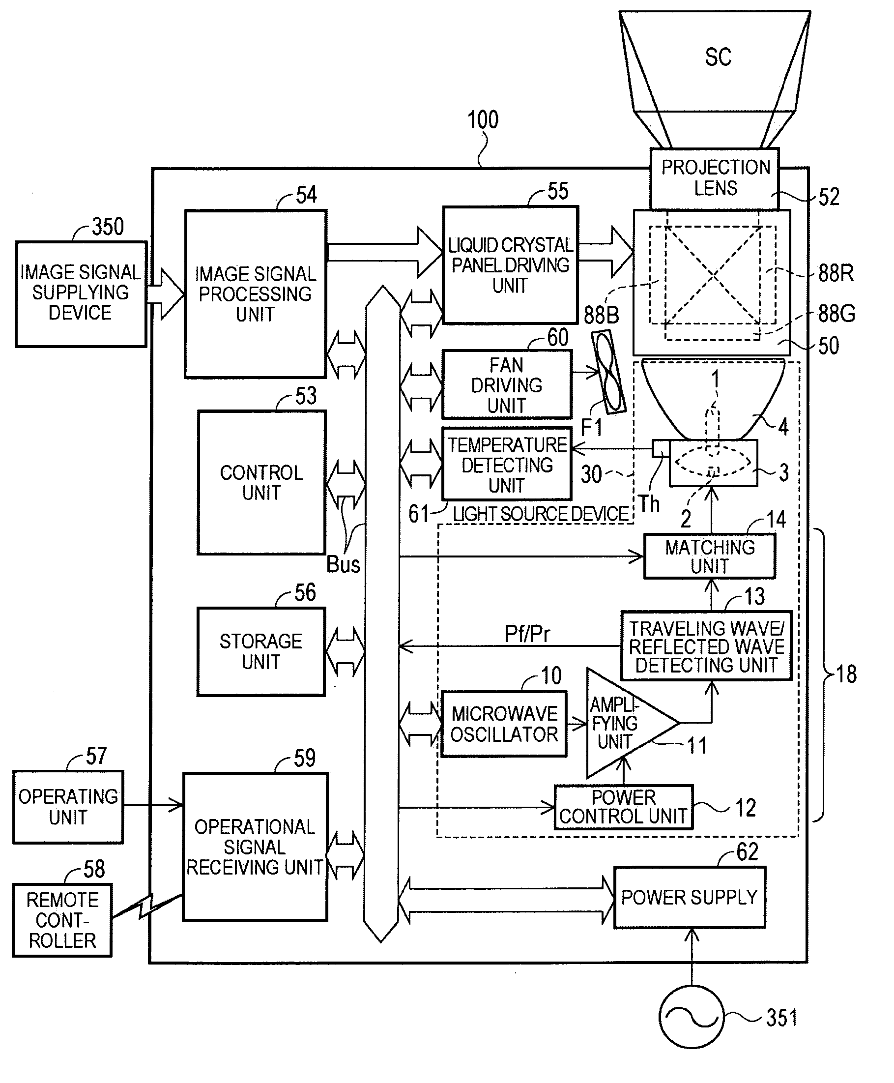
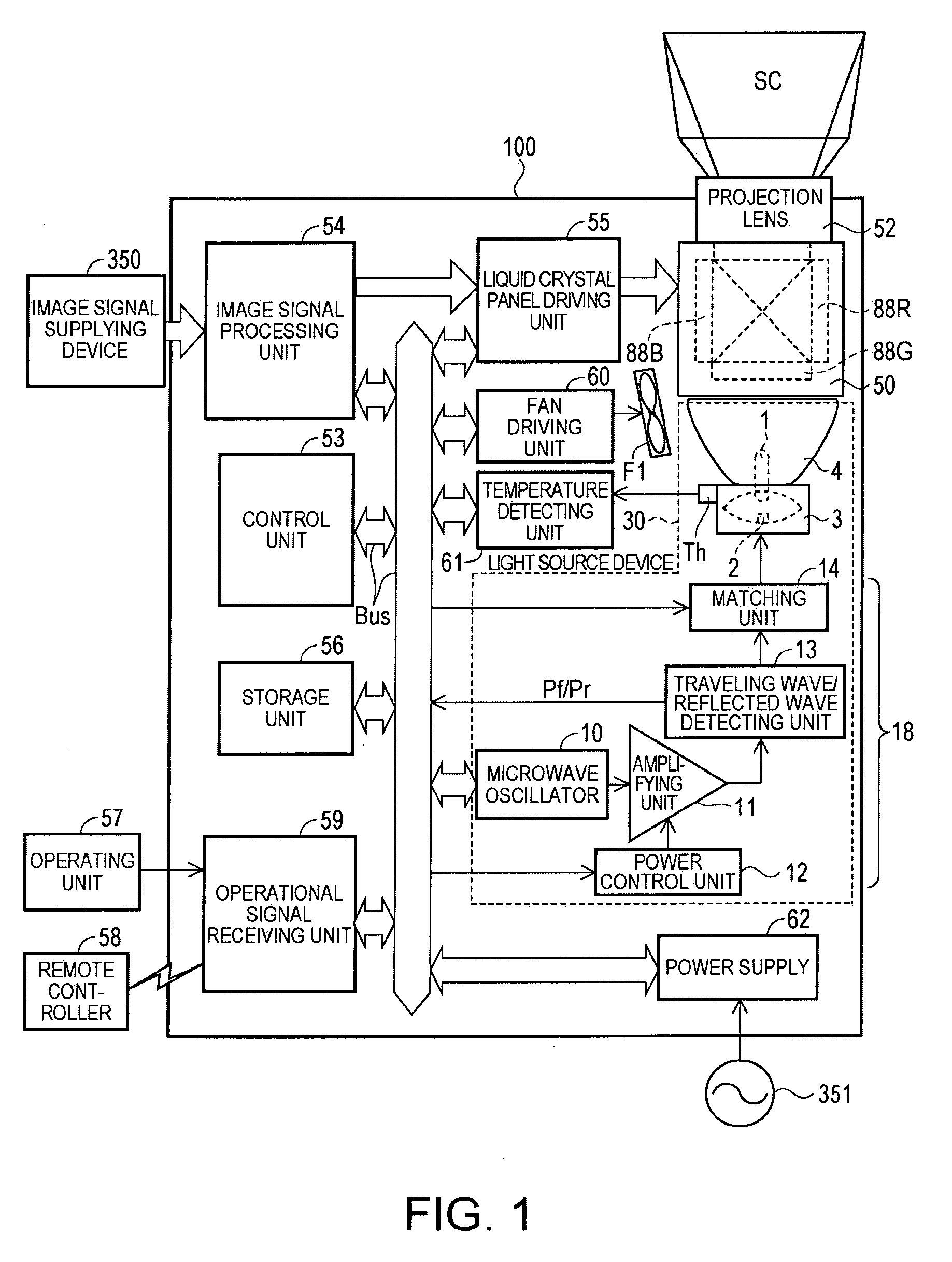
[0041]FIG. 1 is a diagram schematically illustrating the structure of a projector according to a first embodiment of the invention.

[0042] A projector 100 is a so-called projector of a three liquid crystal panel type in which light emitted from a light source device 30 is separated into three color light components, that is, red, green, and blue light components, the separated light components are modulated by red, green, and blue liquid crystal light valves 88R, 88G, and 88B, serving as light modulating devices, according to image signals, the modulated light components are combined into a full color optical image, and the full color optical image is enlarged and projected onto a screen SC by a projection lens 52. The liquid crystal light valves 88R, 88G, and 88B are provided for the red, green, and blue light components, respectively, and are included in the structure of an optical unit 50.

[0043] In the light source device 30, an electrodeless lamp 1, serving as a light emitting ...

second embodiment

[0178]FIG. 10 is a diagram schematically illustrating the structure of a projector according to a second embodiment of the invention.

[0179] A projector 200 according to the second embodiment is similar to the projector 100 according to the first embodiment except for the following three points.

[0180] First, the projector 200 includes a light detecting unit 65.

[0181] Second, the light source device 35 of the projector 200 is provided with an isolator 66 instead of the traveling wave / reflected wave detecting unit 13 (FIG. 1).

[0182] Third, a storage unit 56 of the projector 200 stores programs and data and some of the programs and data are different from those in the projector 100.

[0183] In the second embodiment, the same components as those in the projector 100 according to the first embodiment have the same reference numerals, and the schematic structure of the projector 200 will be described, centered on the above-mentioned three different points.

[0184] The light detecting uni...

first modification

(First Modification)

[0222] A first modification will be described with reference to FIG. 5. In the above-described embodiments, the light source device 30 or the light source device 35 is provided in the projector, but the invention is not limited thereto.

[0223] For example, since the light source device 30 is rapidly and reliably turned on, can stably obtain a desired quantity of light, and has a small size and a light weight, it may be applied to illuminating devices for airplanes, ships, and vehicles and interior illuminating devices.


PUM


Abstract

Task To provide a projector using a light source device that is rapidly and reliably turned on and can stably obtain a desired amount of light and a method of rapidly and reliably turning on a light source device of a projector. Means for Resolution A power control unit adjusts the amplification factor of an amplifying unit for microwaves such that microwave power having a pulse form that is higher than the microwave power radiated to keep an electrodeless lamp emitting light is radiated to turn on the electrodeless lamp. Therefore, a microwave having predetermined power is radiated to the electrodeless lamp at once.

Description

TECHNICAL FIELD [0001] The present invention relates to a projector including a light source device using microwaves and a method of turning on the light source device of the projector. BACKGROUND ART [0002] Projectors for projecting images on the basis of image signals have been used for presentation in the meeting or home theaters. As a light source for the projector, a light source capable of rapidly turning on and stably ensuring the quantity of light with high brightness is used to rapidly obtain a bright projected image, or a light source capable of adjusting the quantity of light without changing an emission spectrum is used to obtain a bright projected image most suitable for a projection environment. [0003] Discharge lamps, such as a halogen lamp, a metal halide lamp, and a high-pressure mercury lamp, have come into widespread use in the projectors on the market. This is because the discharge lamp can obtain high brightness. [0004] The discharge lamp needs discharge electro...

Claims


Application Information

Patent Timeline
IPC IPC(8): G03B21/20F21Y101/00
CPCG03B21/2053G03B21/2006
Inventor TAKAGI, SHIGEKAZUTAKADA, YUTAKAFUJII, SATOSHI
Owner SEIKO EPSON CORP
Why Eureka
Try Eureka