Magnetized drill bit extension

a drill bit and magnet technology, applied in the field of can solve the problems that the magnetized drill bit extension substantially departs from the conventional concepts and designs of the prior, and achieve the effects of convenient application to renovations and repairs, reducing cosmetic and structural damage, and being readily manufactured and efficiently marketed

Inactive Publication Date: 2007-06-07
WELKER ROBERT E
View PDF0 Cites 6 Cited by
  • Summary
  • Abstract
  • Description
  • Claims
  • Application Information

AI Technical Summary

Benefits of technology

[0018] It is another object of the present invention to provide a magnetized drill bit extension that may be readily and efficiently manufactured and marketed.
[0019] It is still another object of the present invention to provide a magnetized drill bit extension that may be readily applied to renovations and repairs in existing structures.
[0020] Still another object of the present invention is to provide a magnetized drill bit extension that passes through less than a three quarter inch diameter hole while minimizing cosmetic and structural damage.

Problems solved by technology

While the above-described devices fulfill their respective, particular objectives and requirements, the aforementioned patents do not describe a magnetized drill bit extension that has a magnetized socket, or a magnet within a socket, that identifies its concealed location to a compass outside a wall.
Further, the magnetized drill bit extension substantially departs from the conventional concepts and designs of the prior art.

Method used


Image

  • Magnetized drill bit extension
  • Magnetized drill bit extension
  • Magnetized drill bit extension

Examples


Embodiment Construction

[0031] The present art overcomes the prior art limitations by providing a magnetized drill bit extension for detecting the same within a structure, typically a residential frame house.

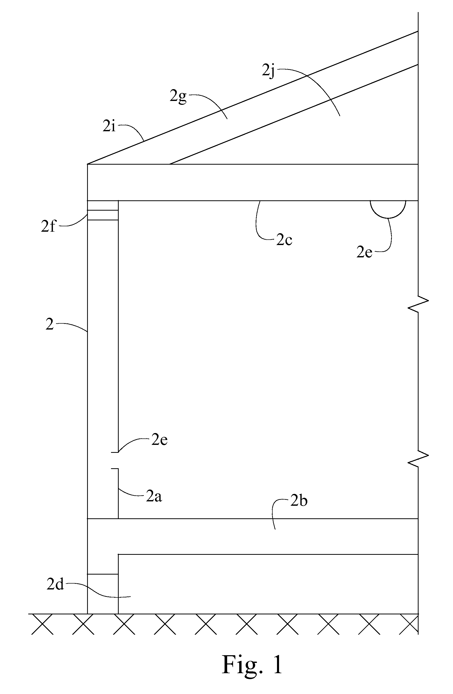
[0032] In FIG. 1, the structure of a house is shown wherein the magnetic drill extension 1 operates. Though the preferred embodiment of the present invention is described in reference to a house 2, the present invention can be used in other structures. The present invention overcomes the obstacles inherent with the intersections of walls 2a, floors 2b, and ceilings 2c. Thus, FIG. 1 shows a house 2 with a crawlspace 2d upon the earth. Above the crawlspace 2d, the house 2 has a floor 2b with a wall 2a at the exterior. The wall 2a has an opening for one or more fixtures 2e. The fixtures 2e can be outlets, switches, and the like. The wall 2a has a cap plate 2f upon the top opposite the floor 2b. The cap plate 2f serves as a support for the ceiling joists. The joists 2c are parallel and separated one story...


PUM

PropertyMeasurementUnit
magneticaaaaaaaaaa
widthaaaaaaaaaa
thicknessaaaaaaaaaa

Abstract

The magnetized drill bit extension provides a socket that accepts bits of various diameters and indicates its location when concealed, as within a wall. The invention has a socket at the end of a drill bit extension with a strong magnet integrated into the socket. The socket accepts round, square, and square corner rounded shanks of bits. The magnet within the socket endures drilling through wood. The socket emanates a magnetic field from within a concealed location that deflects a compass, thus revealing the location of the extension within a wall. Alternatively, a magnet is joined to the spade of a drill bit to reveal its location when concealed.

Description

CROSS REFERENCE TO RELATED APPLICATION [0001] This non-provisional application claims priority to the provisional application Ser. No. 60 / 748,357 filed on Dec. 7, 2005 and to the non-provisional application Ser. No. 10 / 880,399 filed on Jun. 29, 2004 (now U.S. Pat. No. 7,093,822) and all are commonly owned by the same inventor.BACKGROUND OF THE INVENTION [0002] The present invention relates to locating an object within a wall, such as when routing electrical wires through walls. The magnetized drill bit extension has particular utility indicating the location of a hole in a cap plate not visible through a wall. [0003] Before pulling wire in walls, the present invention, in cooperation with a bit, prepares a hole and indicates the location of the hole within a wall. Wire can then be pulled through the hole using a magnetic wire pulling system. Magnetic wire pulling systems assist electricians in routing conduits or wires through intersections of walls and floors, and difficult to reac...

Claims


Application Information

Patent Timeline
Patent Type & Authority Applications(United States)
IPC IPC(8): B23B51/00
CPCB23B51/0009B23B51/126B23B2260/10Y10T408/907B25H1/0078B27G15/00B23B2270/48B23B51/00035
Inventor WELKER, ROBERT E.
Owner WELKER ROBERT E
Why Eureka
Try Eureka