Alignment and locating tool

Inactive Publication Date: 2009-01-15
WELKER ROBERT E
View PDF7 Cites 4 Cited by
  • Summary
  • Abstract
  • Description
  • Claims
  • Application Information

AI Technical Summary

Benefits of technology

[0012]To attain this, the present invention essentially comprises a non-marring cylinder with a pair of magnets, diametrically spaced apart upon the sides of the cylinder and of opposite polarity and using a compass to identify the tool thus indicating its location when concealed prior to pulling wire through a house or other structure. The tool indicates its position and spaces the bit extension tool and bit contained therein from interior faces of adjacent panels of drywall. The magnets are integrated into the cylinder of the tool so that the magnets survive ordinary handling, drilling through wooden structures, and rotation. The tool emanates a magnetic field from within a wall, or concealed location, that deflects a compass, thus revealing the location of the tool.
[0018]It is another object of the present invention to provide an aligning and locating tool that may be readily and efficiently manufactured and marketed.
[0019]It is still another object of the present invention to provide an aligning and locating tool that may be readily applied to renovations and repairs in existing structures.
[0020]Still another object of the present invention is to provide an aligning and locating tool that follows behind the head of an extension bit while minimizing cosmetic and structural damage caused by the head.

Problems solved by technology

Misdirected extension bits can damage adjacent pieces of drywall, necessitating repair or replacement of drywall with all of the associated cost and delay.
While the above-described devices fulfill their respective, particular objectives and requirements, the aforementioned patents do not describe an aligning and locating tool that has a spacer with a magnet, that identifies its concealed location to a compass outside a wall.
Further, the aligning and locating tool substantially departs from the conventional concepts and designs of the prior art.

Method used


Image

  • Alignment and locating tool
  • Alignment and locating tool
  • Alignment and locating tool

Examples


Embodiment Construction

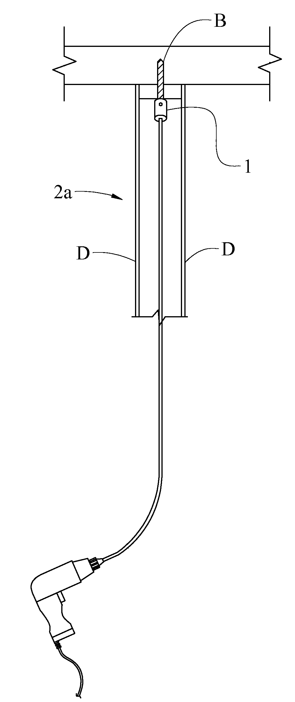
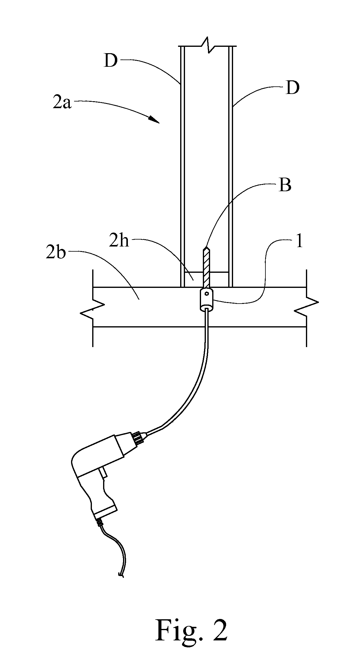
[0032]The present art overcomes the prior art limitations by providing a magnetic cylinder upon a bit extension for detecting the same within a structure, typically a residential frame house.

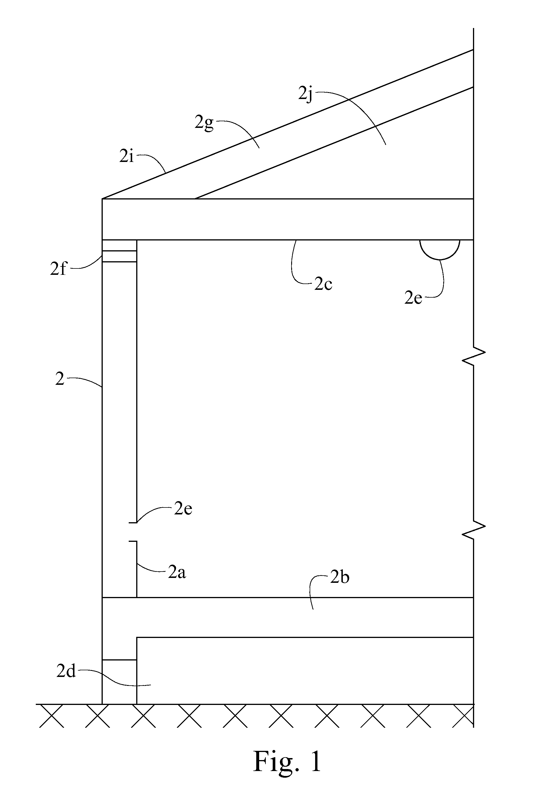
[0033]In FIG. 1, the structure of a house is shown where the magnetic drill extension 1 operates. Though the preferred embodiment of the present invention is described in reference to a house 2, the present invention can be used in other structures. The present invention overcomes the obstacles inherent with the intersections of walls 2a, floors 2b, and ceilings 2c. Thus, FIG. 1 shows a house 2 with a crawlspace 2d upon the earth. Above the crawlspace 2d, the house 2 has a floor 2b with a wall 2a at the exterior. The wall 2a has an opening for one or more fixtures 2e. The fixtures 2e can be outlets, switches, and the like. The wall 2a has a cap plate 2f upon the top opposite the floor 2b and a sill plate 2h. The cap plate 2f serves as a support for the ceiling joists. The joists 2c are parallel ...


PUM


Abstract

A tool has a cylinder with a pair of magnets, diametrically spaced apart upon the sides of the cylinder and of opposite polarity. In cooperation with a compass, the magnets identify the tool thus indicating its location when concealed prior to pulling wire through a house or other structure. The tool also spaces a bit extension tool away from interior faces of adjacent drywall panels. A setscrew secures the cylinder upon the shank of a bit extension for rotation of the tool. The magnets are integrated into the cylinder of the tool to survive ordinary handling, drilling through wooden structures, and rotation. The tool emanates a magnetic field from within a concealed location that deflects a compass for revealing the location of the tool.

Description

CROSS REFERENCE TO RELATED APPLICATION[0001]This non-provisional application claims priority to non-provisional application Ser. No. 11 / 567,611 filed on Dec. 6, 2006 which claims priority to the provisional application Ser. No. 60 / 748,357 filed on Dec. 7, 2005 and to the non-provisional application Ser. No. 10 / 880,399 filed on Jun. 29, 2004 (now U.S. Pat. No. 7,093,822) and all are commonly owned by the same inventor.BACKGROUND OF THE INVENTION[0002]The present invention relates to locating an object within a wall, such as when routing electrical wires through walls. The magnetized drill bit extension has particular utility indicating the location of a drill bit not visible through a wall.[0003]Before pulling wire in walls, the present invention, in cooperation with a bit, prepares a hole and indicates the location of the hole within a wall. Wire can then be pulled through the hole using a magnetic wire pulling system. Magnetic wire pulling systems assist electricians in routing con...

Claims


Application Information

Patent Timeline
IPC IPC(8): H02G1/08
CPCY10T279/3406H02G3/00H02G1/00
Inventor WELKER, ROBERT E.
Owner WELKER ROBERT E
Why Eureka
Try Eureka