

Magnetron
a technology of magnets and tubes, applied in the field of magnets, to achieve the effect of reducing heating power and enhancing efficiency
- Summary
- Abstract
- Description
- Claims
- Application Information
AI Technical Summary
Benefits of technology
Problems solved by technology
Method used
Image

Examples
first embodiment
[0033]Hereinafter, a magnetron according to the present invention will be explained in more detail.
[0034]The same reference numerals will be given to the same parts as the aforementioned parts.
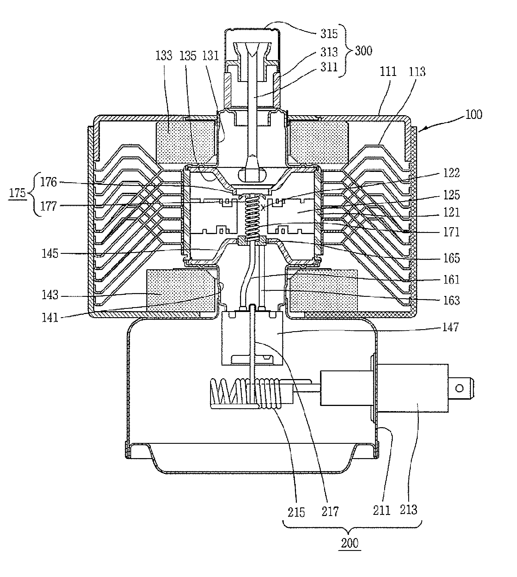
[0035]As shown in FIGS. 4 to 6, the magnetron according to the present invention comprises a high frequency generating unit 100 interposed between an input unit 200 for providing power and an output unit 300 for outputting high frequency energy, for generating high frequency. The high frequency generating unit 100 includes an anode having a cylindrical shape; a plurality of vanes 125 disposed in the anode 121; an upper magnetic pole 135 and a lower magnetic pole 145 respectively disposed at an upper side and a lower side of the anode 121; a cathode 171 having a spiral shape, disposed at the center of the anode 121, and passing a center lead 161 therethrough; a lower end shield 165 for passing the center lead 161, and connected to a lower end of the cathode 171; and an upper end shield 175 incl...
second embodiment
[0051]FIG. 8 is a sectional view showing a magnetron according to the present invention, FIG. 9 is an enlargement view showing a main part of FIG. 8, and FIG. 10 is a side view showing a cathode of FIG. 8.
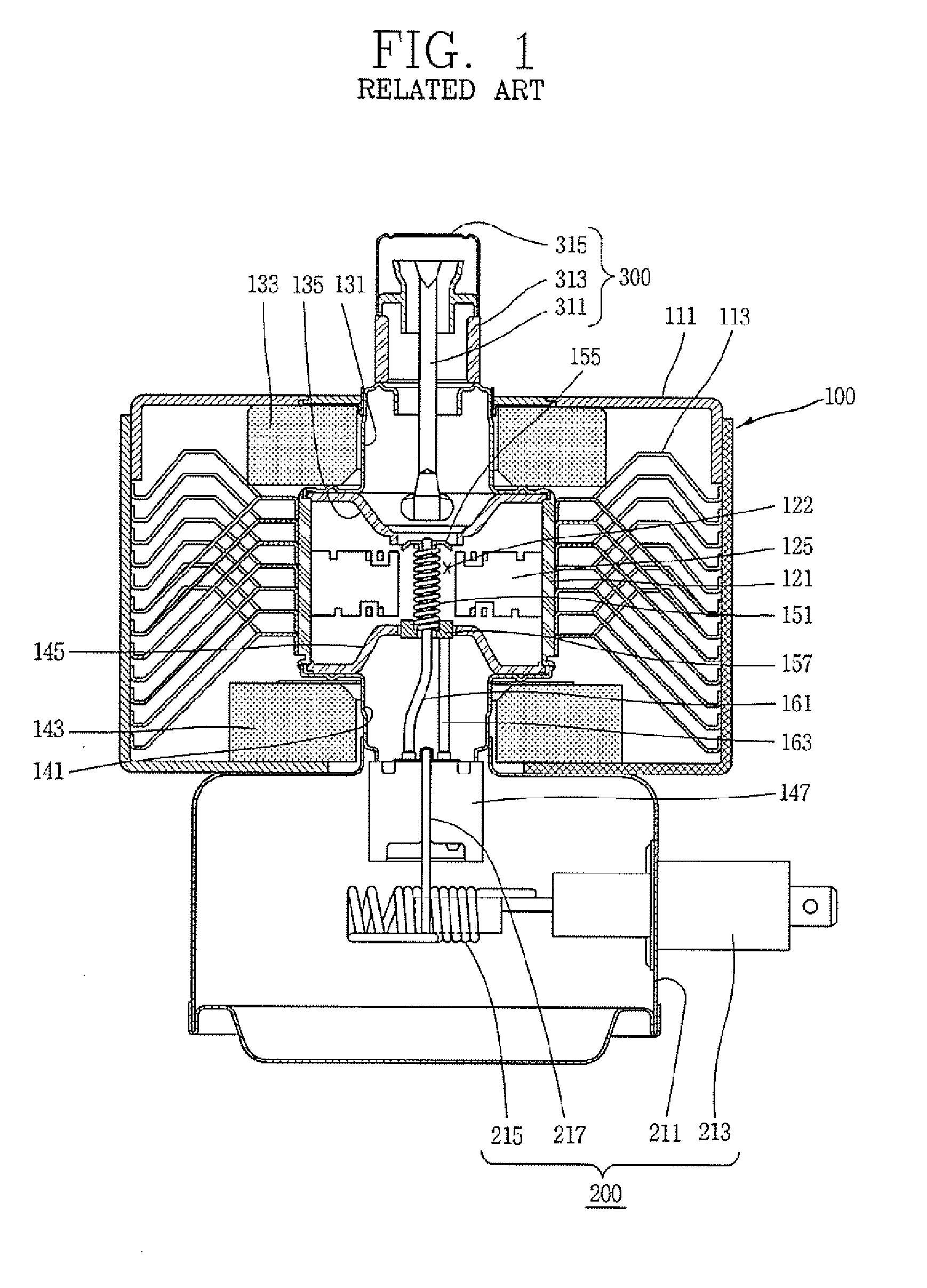
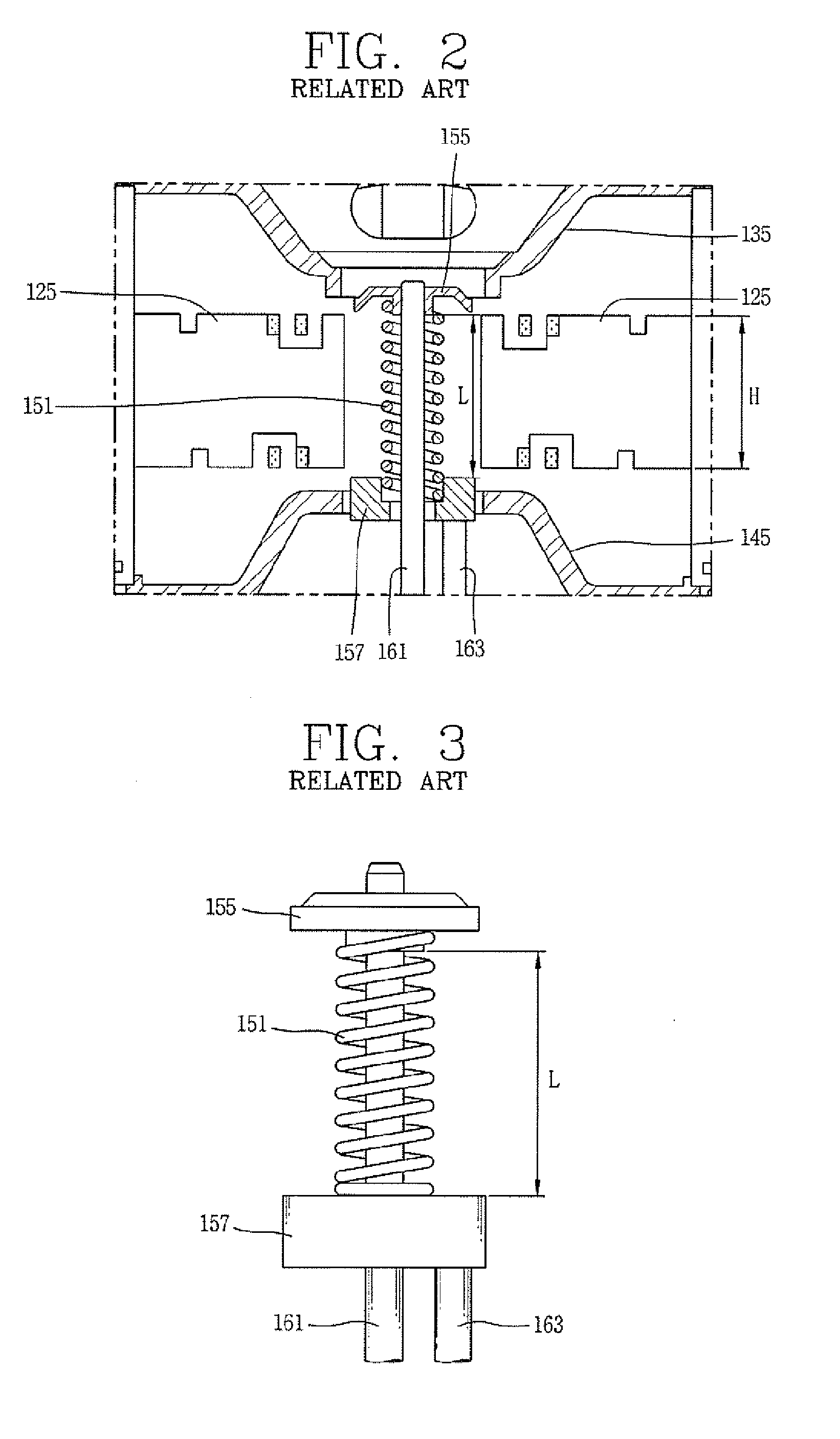
[0052]As shown, the magnetron according to the second embodiment of the present invention comprises an anode 121, a cathode 172 disposed at the center of the anode 121 and passing a center lead 161 therethrough, a plurality of vanes 125 radially protruding from an inner surface of the anode 121 towards the cathode 172, and an upper end shield 155 and a lower end shield 185 respectively coupled to an upper end and a lower end of the cathode 172 so that a length L of an effective heating portion of the cathode 172 may be less than a height H of the vane 125.
[0053]A yoke plate 111 is provided at an outer side of the anode 121, and a plurality of cooling fins 113 are coupled to inside of the anode 121 and the yoke plate 111.
[0054]An input unit 200 for applying power to the high frequen...
third embodiment
[0063]FIG. 11 is a sectional view showing a magnetron according to the present invention, and FIG. 12 is an enlargement view showing a main part of FIG. 11.
[0064]As shown, the magnetron according to the third embodiment of the present invention comprises an anode 121, a cathode 173 disposed at the center of the anode 121 and passing a center lead 161 therethrough, a plurality of vanes 125 radially protruding from an inner surface of the anode 121 towards the cathode 173, and an upper end shield 195 and a lower end shield 205 respectively coupled to an upper end and a lower end of the cathode 173 so that a length L of an effective heating portion of the cathode 173 may be less than a height H of the vane 125.
[0065]A yoke plate 111 is provided at an outer side of the anode 121, and a plurality of cooling fins 113 are coupled to inside of the anode 121 and the yoke plate 111.
[0066]An input unit 200 for applying power to the high frequency generating unit 100 is formed at a lower side o...
PUM
| Property | Measurement | Unit |
|---|---|---|
| Length | aaaaa | aaaaa |
| Size | aaaaa | aaaaa |
| Shape | aaaaa | aaaaa |
Abstract
Description
Claims
Application Information