System and method for determining the leakproofness of an object

a leakproofness and object technology, applied in the field of systems for determining the leakproofness of objects, can solve the problems of high operator dependence, high cost, and limited sensitivity of low-cost methods, and achieve the effects of reducing the cost of geometrical volume reduction, high vacuum system complexity, and high operator dependen

Active Publication Date: 2007-07-12
INFICON AB
View PDF12 Cites 34 Cited by
  • Summary
  • Abstract
  • Description
  • Claims
  • Application Information

AI Technical Summary

Benefits of technology

[0038] Thanks to that the method further comprises that the step of detecting said tracer gas is preceded by a step of introducing a transport gas other than said tracer gas into the one of the cavities rendered the lower pressure by introduction means for transporting any tracer gas in the second cavity towards the detecting means via the evacuating means, a step of compressing gas arriving at the

Problems solved by technology

These two methods are simple, low cost methods, but with restricted sensitivity and high operator dependence.
However, the cost for geometrical volume reduction increases rapidly with smaller volume and particularly if the geometry of the test object is complex.
However, high vacuum systems require advanced pumps and valves that are both delicate and costly.
Experience shows also that such systems are very difficult and costly to maintain in normal industrial environments.
Furthermore, mass spectrometers which often are used for detection in vacuum chamber testing are very expensive and complicated and therefore costly to maintain.
Thus, both capital investments and maintenance costs for vacuum chamber testing are high.
However, testing at atmospheric pressure implies a low test speed and a relatively low sensitivity if the dead volume is not reduced.
Since the costs for geometrical volume reduction of the dead volume in the enclosure, as mentioned above, is high, testing at atmospheric pressure is generally not suitable for

Method used


Image

  • System and method for determining the leakproofness of an object
  • System and method for determining the leakproofness of an object
  • System and method for determining the leakproofness of an object

Examples


first embodiment

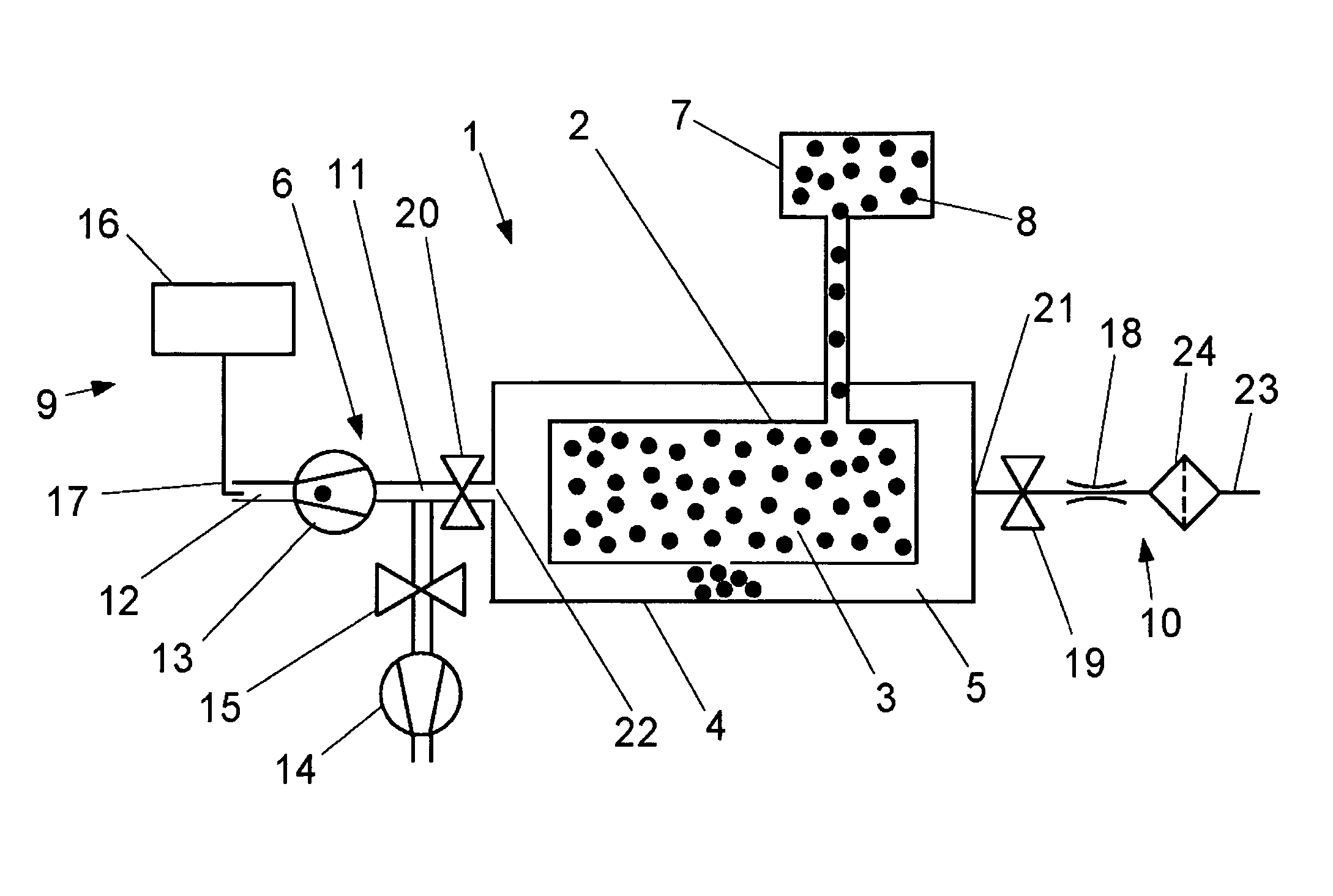
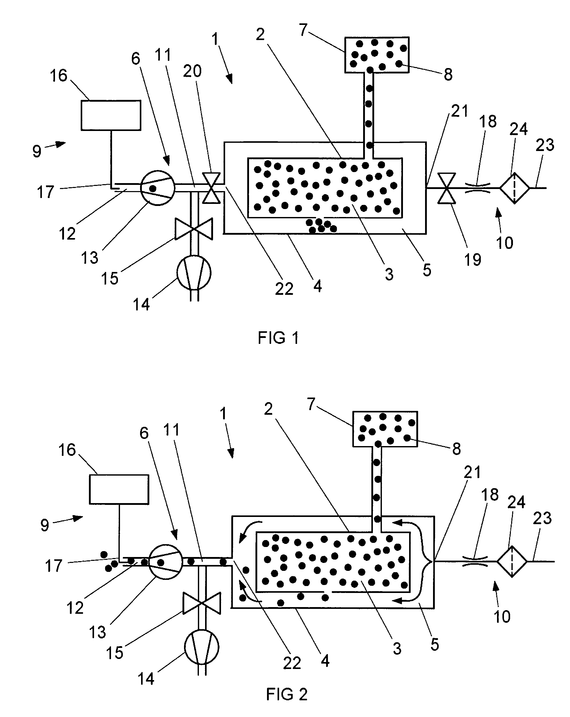
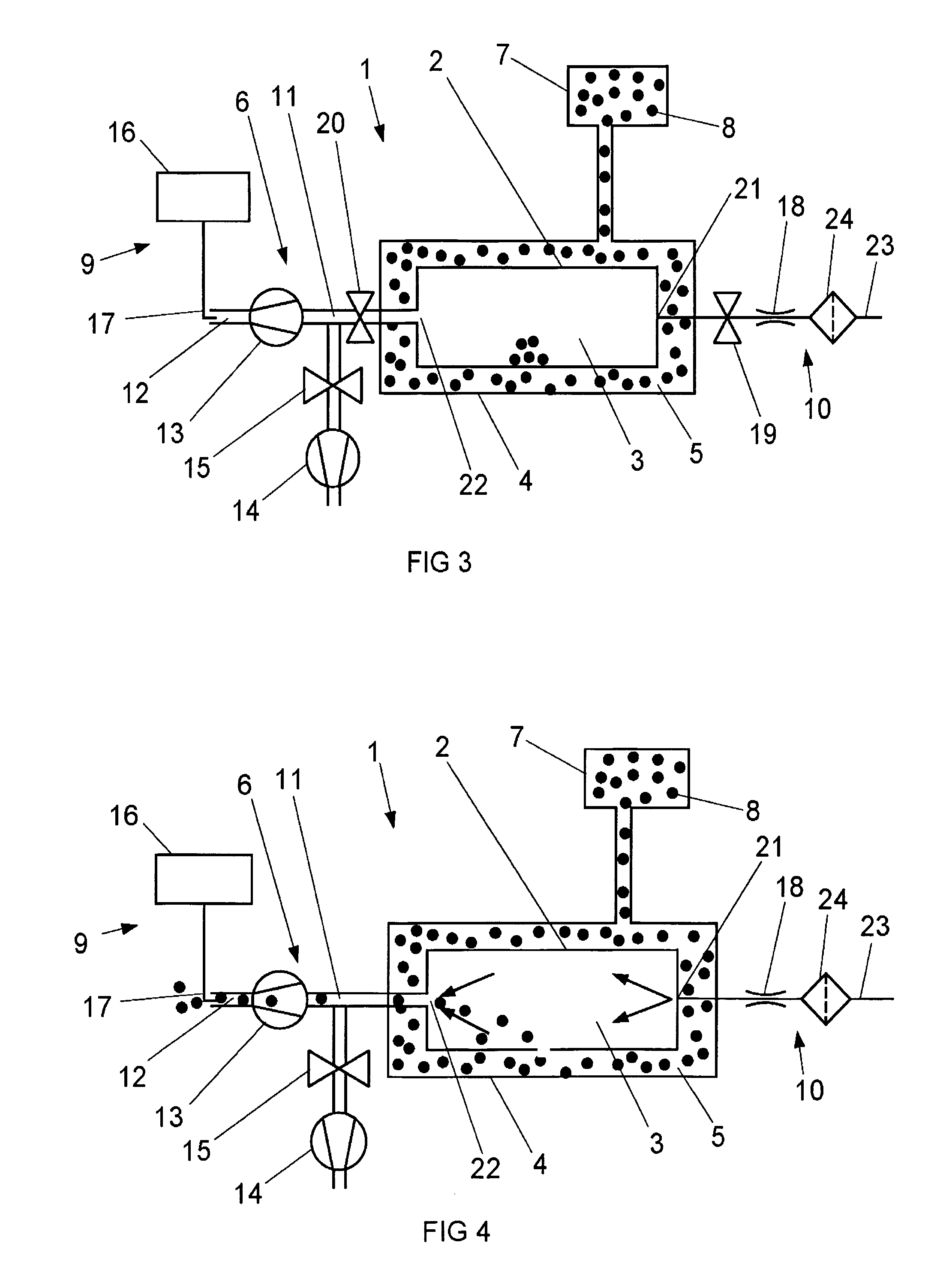
[0046]FIG. 1 shows a system 1 in accordance with the present invention, which system 1 is arranged to be used for determining the leakproofness or the impermeability of an object 2 having a first cavity 3. the system 1 is suited to be used for applying a tracer gas method in which the object to be tested is placed in a chamber or enclosure. More particularly, the system 1 is suited to be used for applying the above described accumulation method. The system 1 comprises a closed chamber or enclosure 4 having a second cavity 5, evacuating means 6, supplying means 7 for supplying a tracer gas 8, detecting means 9 being sensitive to the tracer gas 8 and introduction means 10 for introducing a transport gas.

[0047] The chamber 4 is arranged to envelope the object 2 to be tested for leakage within the second cavity 5, which therefore has such a size and shape that it is able to accommodate the object 2 to be tested. When the object 2 is located within the second cavity 5, there is also some...

third embodiment

[0073] In order to be able to test leakage from the second cavity 5 and into the first cavity 3, the supplying means 7 is then arranged to supply the tracer gas 8 to the second cavity 5 and the detecting means 9 is arranged to detect any tracer gas in the first cavity 3. Thus, the detecting means 9 is then arranged to communicate with the first cavity 3 through the evacuating means 6. Furthermore, the introduction means 10 is arranged to introduce the transport gas into the first cavity 3 towards the detecting means 9. The inlet 21 is in the third embodiment located between the flow regulating means 18 and the object 2 and the outlet 22 is located between the object 2 and the inlet 11 of the evacuating means 6.

[0074]FIG. 4 shows a fourth embodiment of the system 1, which is arranged to be used for leakage testing applying the above described steady-state analysis method. The fourth embodiment resembles the third embodiment except for concerning the introduction means 10, the first v...

fifth embodiment

[0086] Furthermore, in an alternative of the fifth embodiment, the method comprises at least two steps of introducing transport gas during one controlled time interval, which steps are performed in sequence. If the pulse is transported towards the detecting means by means of the evacuating means, then the method also comprises an evacuation time interval for each step of introducing transport gas.

[0087] The invention is not limited to the above-described embodiments, but may be varied within the scope of the following claims. For example, it might be a part of one object that is the object to be tested and the ambient pressure of the chamber might be another pressure than the atmospheric pressure. Furthermore, the introduction means may be arranged to introduce the transport gas during more than one controlled time interval. The evacuating means may comprise other types of pumps than those specifically mentioned and the detecting means may be configured in other ways than those ment...


PUM


Abstract

A system and a method for determining the leakproofness of an object having a first cavity. The system includes a closed chamber having a second cavity arranged to envelope the object, an evacuator for lowering the pressure inside one of the cavities, a supply for supplying a tracer gas into the one of the cavities rendered the higher pressure, a detector sensitive to the tracer gas and an introducer for introducing a transport gas into the one of the cavities rendered the lower pressure. Furthermore, the evacuator is arranged to compress arriving gas to the ambient pressure of the chamber and to communicate with the detecting means, which is suited for operation at the ambient pressure of the chamber. The tracer gas is hydrogen.

Description

FIELD OF THE INVENTION [0001] The present invention relates to a system for determining the leakproofness of an object in accordance with the preamble of claim 1. Furthermore, the present invention relates to a method for determining the leakproofness of an object in accordance with the preamble of claim 13. BACKGROUND OF THE INVENTION [0002] The leakproofness of an object might be necessary or desired to determine for different reasons. For example, the leakproofness might be required to be tested due to environmental concern or quality control. The number of industrial products and utilities required to be tested for leakage has greatly increased during the recent years, which above all depends on increased demands on environmental concern and improved quality. Typical examples of products required to be tested for leakage are parts of refrigeration systems for commercial, domestic and automotive use as well as all types of liquid and gas carrying parts in the automotive industry,...

Claims


Application Information

Patent Timeline
IPC IPC(8): G01M3/20G01M3/22
CPCG01M3/226
Inventor JENNEUS, PERENQUIST, FREDRIK
Owner INFICON AB
Why Eureka
Try Eureka