Medical clip feeding mechanism

a technology of feeding mechanism and medical clip, which is applied in the field of feeding mechanism of medical clip, surgical stapler, etc., can solve the problems of increasing costs, slipping of ladder inadvertently, and complicating surgical process, so as to achieve the effect of resistan

Inactive Publication Date: 2007-08-09
MICROLINE PENTAX
View PDF27 Cites 209 Cited by
  • Summary
  • Abstract
  • Description
  • Claims
  • Application Information

AI Technical Summary

Benefits of technology

[0019] Accordingly, it is a feature of the present invention to generate appropriate resi

Problems solved by technology

However, because the ladder typically has a mass sufficient to slide the ladder along the barrel of the surgical stapler when gravity or inertia acts upon the ladder, there is the possibility that the ladder may slip forward inadvertently while the surgical stapler is in use—for example when the surgeon using the surgical stapler tilts the surgical stapler at an angle steep enough to cause gravity to slide the ladder distalward (that is, toward the distal end) down the barrel.
As such, clips may be unintentionally pushed by the ladder and dropped from the surgical stapler, which can complicate the surgical process and which can lead to increased costs.
However, as discussed above, use of a such a clip applying device with inadequate sliding movement control includes the risk that a staple or clip may be inad

Method used


Image

  • Medical clip feeding mechanism
  • Medical clip feeding mechanism
  • Medical clip feeding mechanism

Examples


first embodiment

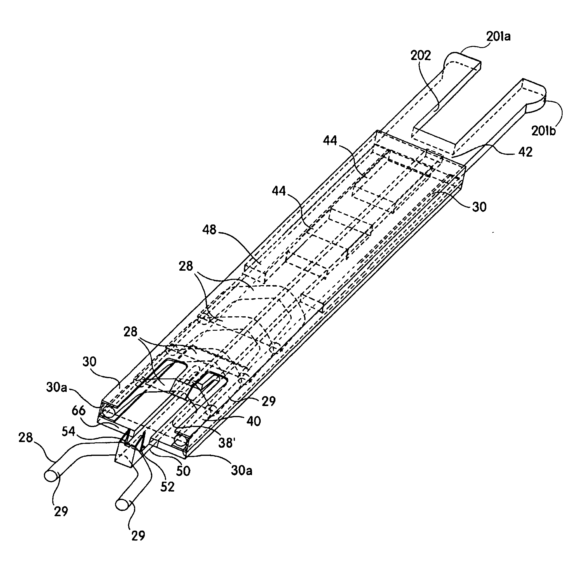
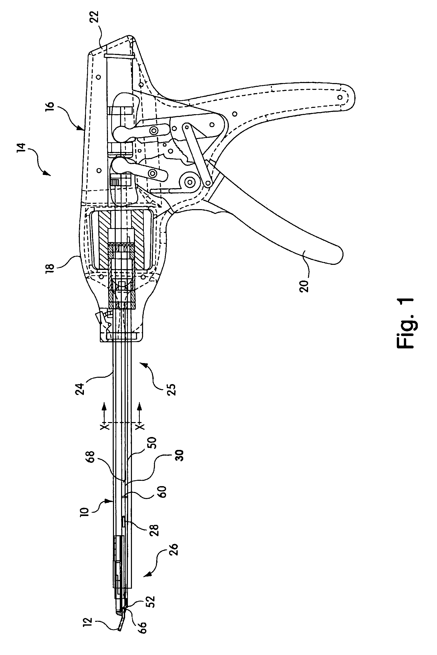
[0056] In accordance with the present invention, a stapling gun 14 (as shown in FIG. 1, for example) may include a clip or staple advancing and feeding arrangement 10 for providing clips or staples to the jaws 12 of the stapling gun 14, for example. A ladder 42 may be generally positioned within a barrel 24, which has a distal end 26 generally proximal to or aligned toward the distal end of the stapling gun 14 that includes the jaws 12, for example, and a proximal end generally proximal to, aligned toward, an / dor abutting the housing 18 of the handle 16.

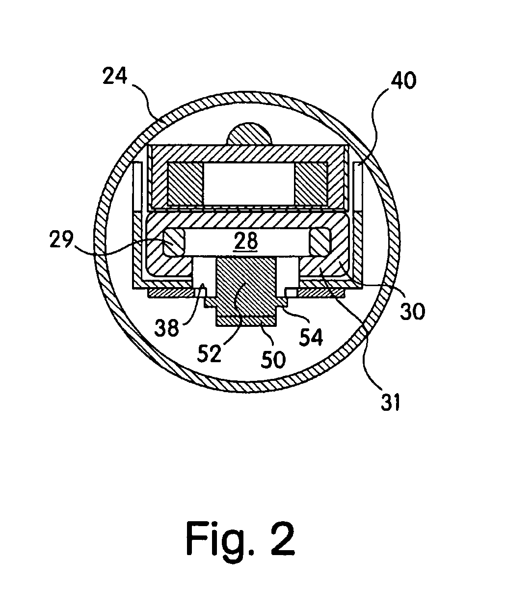
[0057] The barrel 24 may be flexible or, alternatively, may be rigid, for example, or may have any appropriate properties of flexibility and / or rigidity. Also, the barrel 24 may have a cross-section of any suitable shape or form. As illustrated in FIG. 2, in a non-limiting example, at least one embodiment of the present invention may include a barrel 24 with a generally circular and / or elliptical cross-section—however, the barrel 24 ...

second embodiment

[0068] In accordance with the present invention, for example, the distal end 103 of the ladder 42 includes distal protrusions 48a and 48b extending from both side-rails of the ladder 42 (see FIGS. 12, 13 and 14, for example), which are elastically biased outward (that is, laterally) away from the center axis of the ladder 42 by the elasticity inherent in the material of which the ladder 42 is composed. As shown in FIG. 12, for example, the distal protrusions 48a and 48b may be naturally biased outward from the straight axes of both side-rails (the respective straight axes of which are parallel to one another) of the ladder 42 by an angle θD, such that when the ladder 42 is enclosed by the cartridge 30, the inner side walls 30a of the cartridge 30 elastically deform the distal protrusions 48a and 48b back toward the central axis of the ladder 42.

[0069] In such a state, the elasticity of the distal protrusions 48a and 48b (see FIG. 12) causes them to abut against the side walls 30a of...

third embodiment

[0075]FIG. 16 also illustrates an alternative configuration of the present invention, in which the distal protrusions 48a and 48b of the ladder 42 form a shape generally similar to a letter ‘V,’ for example, although various other shapes or forms may also be selected, such as a partial hexagonal shape similar to a wrench-head, for example, or any other suitable form.

[0076]FIGS. 17 and 18 illustrate a fourth embodiment of the present invention, in which the end portion (including, in the exemplified embodiments, the distal protrusions 48a and 48b) of the ladder 42 forms an abutment portion and in which the clips 28 are designed having a form or shape that conforms to the abutment portion of the ladder 42. Examples of these are parabolic or semicircular shape, as shown in FIG. 9A, or an angled shape, as shown in FIG. 9B, for example (and similar to the exemplary shapes discussed above in regard to the third embodiment).

[0077] Because of the conformation of the clips 28 to the abutmen...


PUM


Abstract

A ladder for use with a clip applying device may include first and second protrusions extending from an end of the ladder along a lateral plane generally coplanar with the ladder or an orthogonal plane generally orthogonal to the ladder, in which the ladder may serially urge a clip outward from the surgical stapler, and the first and second protrusions may abut a cartridge in which the ladder is disposed.

Description

1. FIELD OF THE INVENTION [0001] This invention relates to feeding arrangements for medical clip and stapling devices, and more particularly to a surgical stapler for the pinching, stapling, metal suturing or clipping of blood vessels or for the closure of wounds, in which the surgical stapler includes a ladder-type feeding mechanism. The invention also relates to the ladder-type feeding mechanism and cartridge containing the ladder and clips. 2. BACKGROUND OF THE INVENTION [0002] Surgical staplers and clips have been used with increasing frequency to replace suturing and / or for closing wounds or to tie-off blood vessels during a surgical procedure or other traumatic medical event. Such surgical staplers generally have a pair of jaws at a distal end of the surgical stapler (that is, the end opposite the handle, trigger, or other actuation assembly for manipulation by the user), which crimp a generally U-shaped clip flatly across the tissues to be tied or sutured. Typically, the clip...

Claims


Application Information

Patent Timeline
IPC IPC(8): A61B17/10
CPCA61B17/1285A61B17/068
Inventor MANETAKIS, EMMANUELALISKI, PETER
Owner MICROLINE PENTAX
Why Eureka
Try Eureka