Wireless transceiver system

a transceiver and wireless technology, applied in the field of communication systems, can solve the problems of loss of connectors and cable loss in transportation

Inactive Publication Date: 2007-09-13
HON HAI PRECISION IND CO LTD
View PDF9 Cites 23 Cited by
  • Summary
  • Abstract
  • Description
  • Claims
  • Application Information

AI Technical Summary

Problems solved by technology

The transport loss includes a cable loss and a connector loss.

Method used


Image

  • Wireless transceiver system
  • Wireless transceiver system
  • Wireless transceiver system

Examples


Embodiment Construction

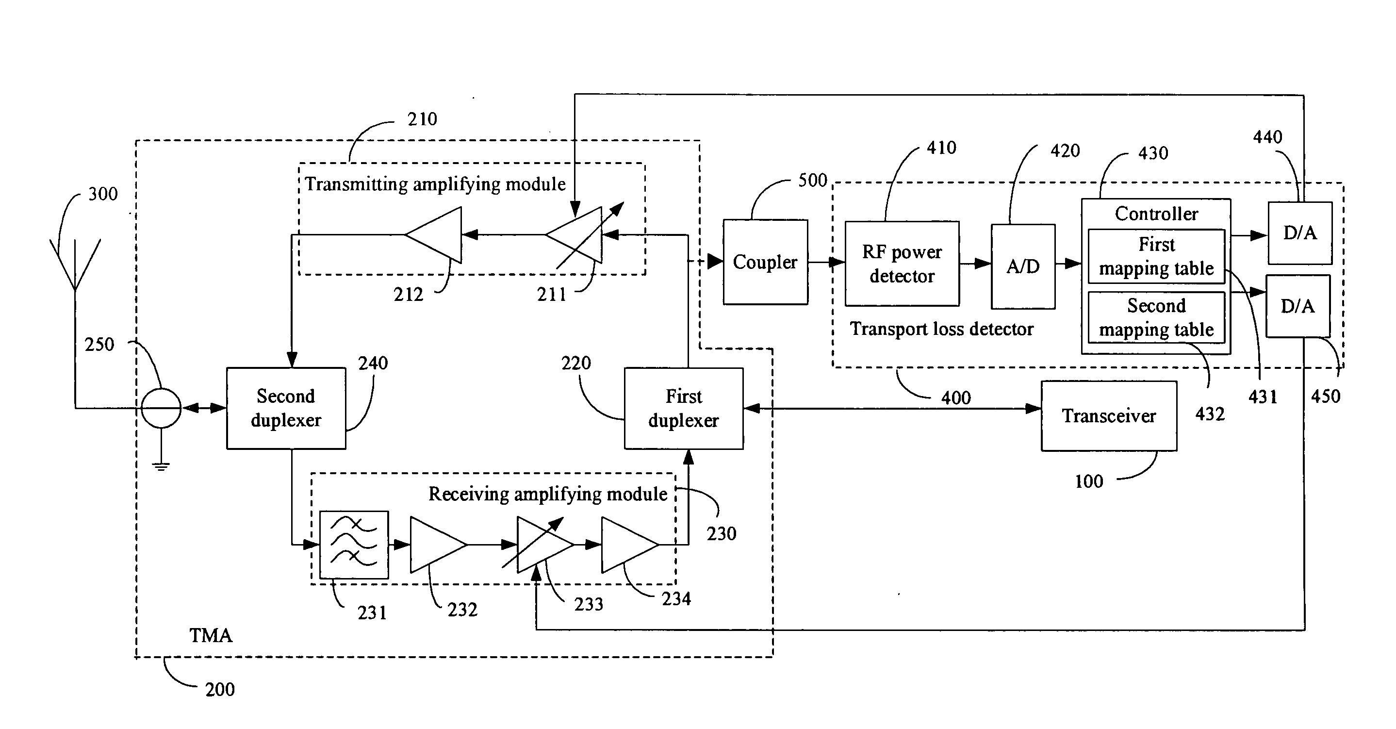
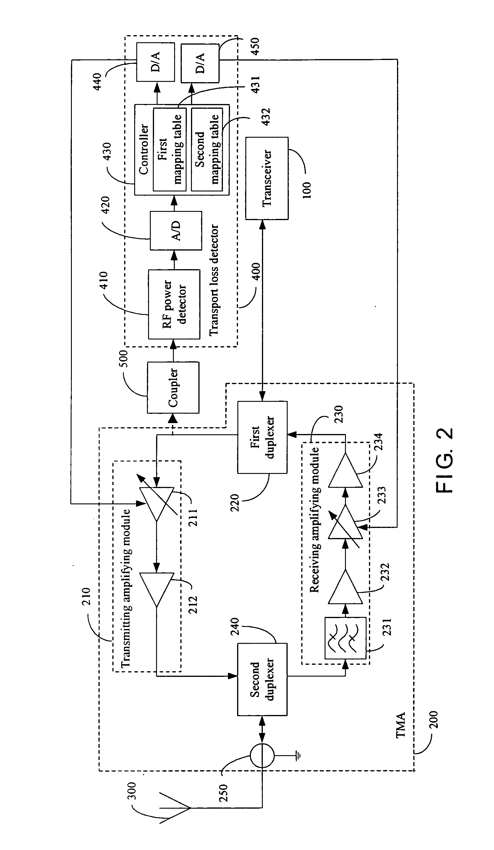
[0011]FIG. 2 is a schematic diagram of functional modules of a wireless transceiver system of an exemplary embodiment of the invention. In the exemplary embodiment, the wireless transceiver system is in a frequency division duplex (FDD) mode. The wireless transceiver system can accurately compensate a transport loss, and includes a transceiver 100, a tower mounted amplifier (TMA) 200, an antenna 300, and a transport loss detector 400. The antenna 300 and the TMA 200 are located on an outdoor tower outside a building, and the TMA 200 is connected to the antenna 300. The transceiver 100 is disposed indoors, i.e., inside the building. The transceiver 100 is connected to the TMA 200 via a cable. Therefore, there is a transport loss between the transceiver 100 and the TMA 200. In the exemplary embodiment, the transport loss includes a cable loss and a connector loss. In other embodiments, the transport loss may include other losses.

[0012]The antenna 300 transmits and receives signals. Th...


PUM


Abstract

A wireless transceiver system for compensating a transport loss includes a transceiver (100), a tower mounted amplifier (TMA) (200), and a transport loss detector (400). The transceiver transmits a first signal at a transmit power. The first signal is changed into a second signal after cable attenuation from the transceiver. The TMA is connected to the transceiver via a cable, receives a second signal, and amplifies the second signal. The transport loss detector is connected to the TMA, and calculates a transport loss between the transceiver and the TMA. The TMA further compensates the transport loss between the transceiver and the TMA according to the calculated result of the controller.

Description

BACKGROUND OF THE INVENTION[0001]1. Field of the Invention[0002]The invention relates to communication systems, and particularly to a wireless transceiver system.[0003]2. Description of Related Art[0004]FIG. 1 is a schematic diagram of a conventional wireless transceiver system. The conventional wireless transceiver system includes a transceiver 10, a tower mounted amplifier (TMA) 20, and an antenna 30. The antenna 30 and the TMA 20 are located on an outdoor tower outside a building, and the TMA 20 is connected to the antenna 30. The transceiver 10 is disposed inside the building. The transceiver 10 is connected to the TMA 20 via a cable. Therefore, there is a transport loss between the transceiver 10 and the TMA 20. The transport loss includes a cable loss and a connector loss.[0005]The transport loss between the transceiver 10 and the TMA 20 cannot be accurately measured, so the TMA 20 cannot accurately compensate the transport loss. As a result, an output power of the TMA 20 may ...

Claims


Application Information

Patent Timeline
Patent Type & Authority Applications(United States)
IPC IPC(8): H04B7/185H04B17/00
CPCH04W52/367
Inventor WONG, KWO-JYRCHIU, MU-JUNGPIEH, JANE-YI
Owner HON HAI PRECISION IND CO LTD
Why Eureka
Try Eureka