Image processing method, image processor, and image processing program

a technology of image processing and image processing program, which is applied in the field of image processing method, image processing program, and image processing method, can solve the problems of inability to apply separation methods utilizing color characteristics, inability to separate well, and inability to apply to a subject with diffuse reflection textur

Inactive Publication Date: 2007-09-27
SOVEREIGN PEAK VENTURES LLC
View PDF8 Cites 44 Cited by
  • Summary
  • Abstract
  • Description
  • Claims
  • Application Information

AI Technical Summary

Benefits of technology

[0045] According to the present invention, the diffuse and specular reflection components can be separated from images obtained by shooting a subject through a polarizing filter even under an ordinary illumination condition.

Problems solved by technology

The methods, however, cannot separate them well when the object color is similar to the illumination color or another object is reflected by inter-reflection.
Further, when a subject is made of metal, the separation methods utilizing the color characteristics cannot be applied because some kinds of metal have so large wavelength dependencies of a Fresnel coefficient that the specular reflected light and the illumination light do not agree with each other in color vector.
This method stands on the assumption that the diffuse reflection component is uniform in a region where specular reflection is present and, therefore, cannot be applied to a subject having texture of diffuse reflection.
This method, however, cannot remove specular reflected light from light other than completely polarized illumination light and, therefore, is utilized only in a mat and black light blocking box, which means inapplicability to a general condition.

Method used


Image

  • Image processing method, image processor, and image processing program
  • Image processing method, image processor, and image processing program
  • Image processing method, image processor, and image processing program

Examples


embodiment 1

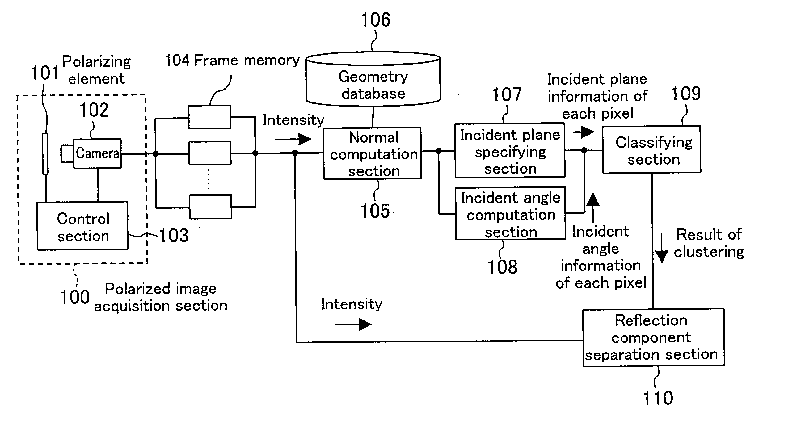
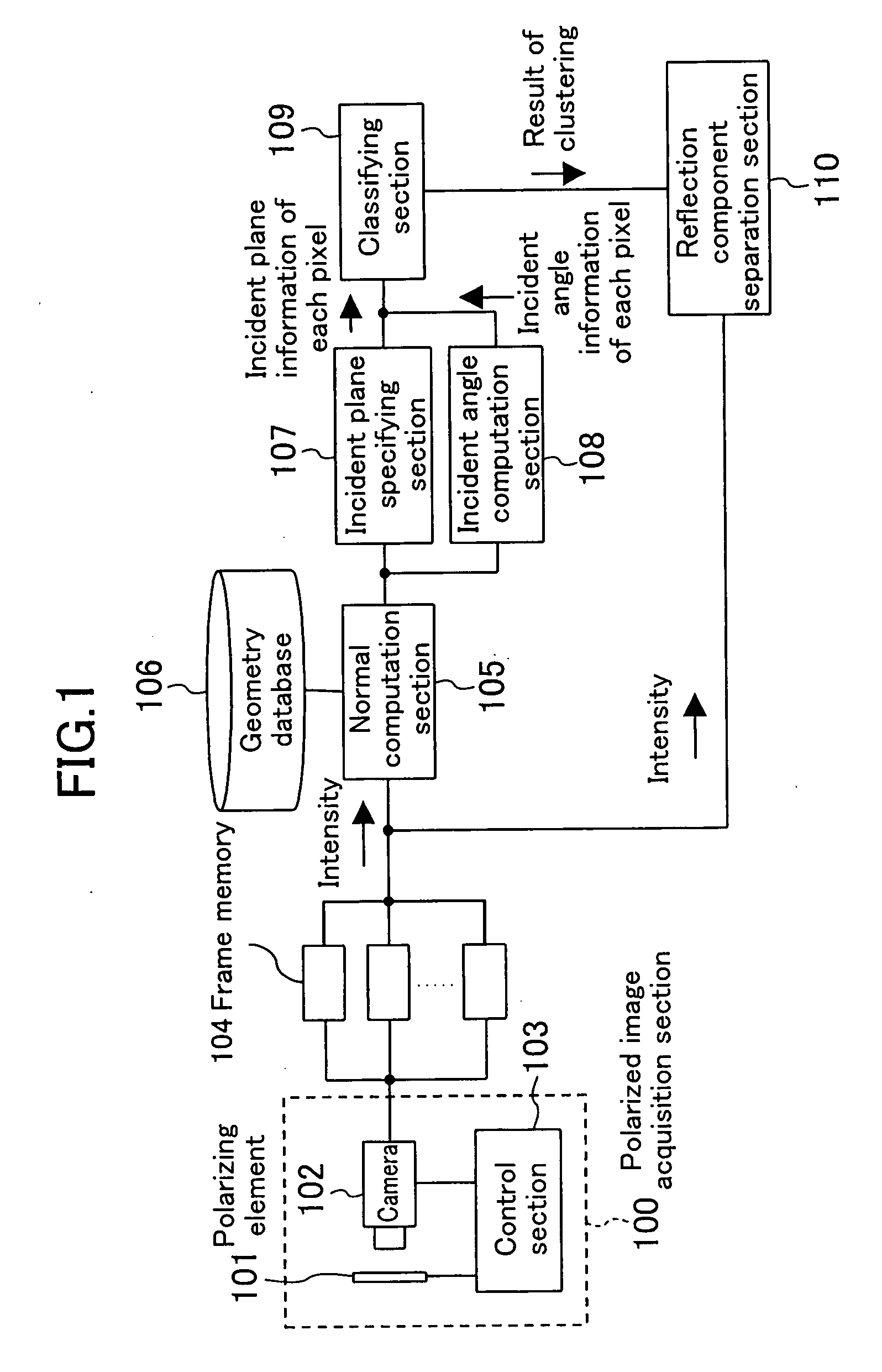
[0102]FIG. 1 is a block diagram showing a configuration of an image processor that executes an image processing method according to Embodiment 1 of the present invention.

[0103] The image processor includes a polarized image acquisition section 100, a frame memory 104, a normal computation section 105, a geometry database 106, an incident plane specifying section 107, an incident angle computation section 108, a classifying section 109, and a reflection component separation section 110. The polarized image acquisition section 100 includes a polarizing element 101, a camera 102, and a control section 103.

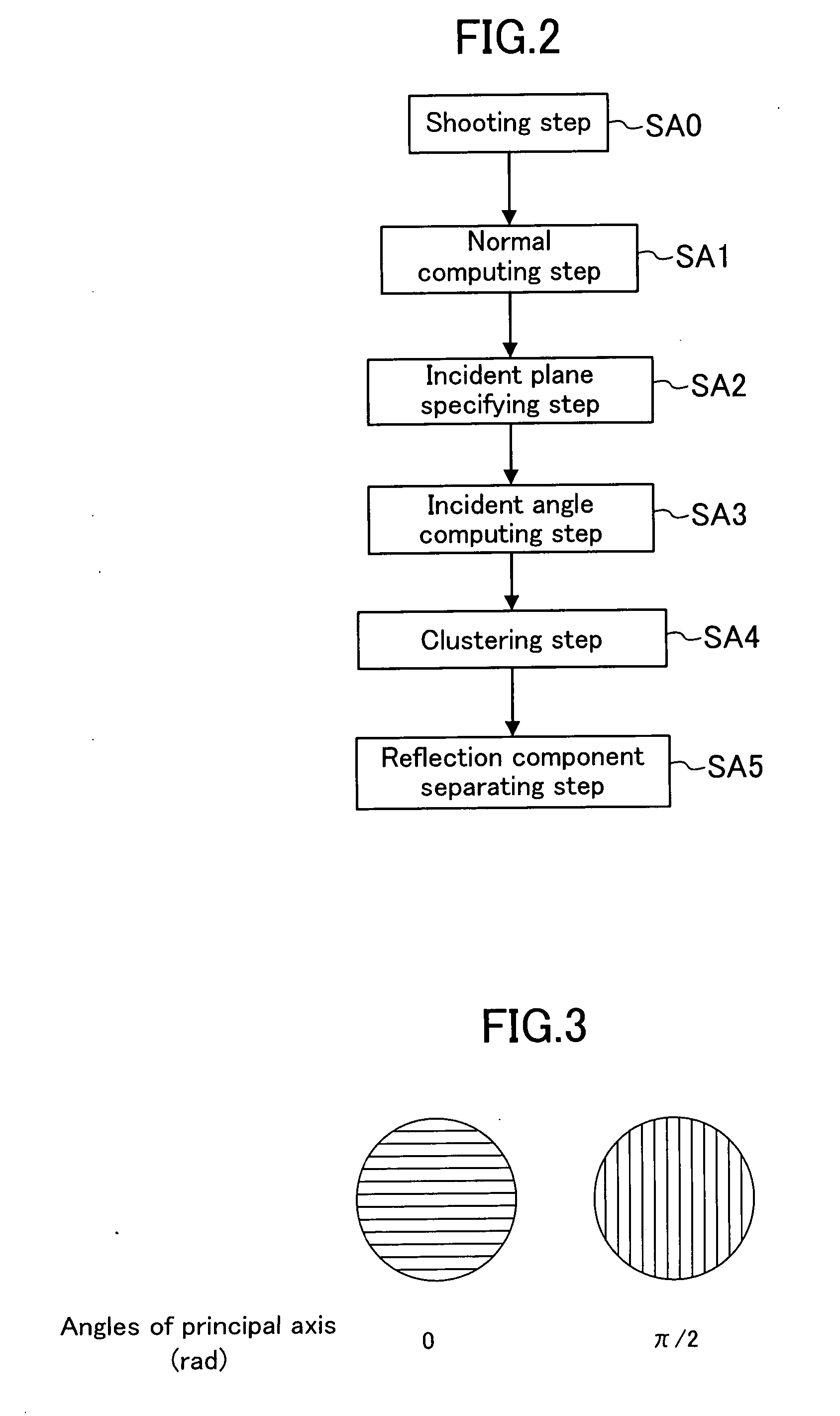
[0104]FIG. 2 is a flowchart of the image processing method according to Embodiment 1 of the present invention.

[0105] The image processing method and the image processor according to the present embodiment will be described below with reference to the block diagram of FIG. 1 and the flowchart of FIG. 2.

[0106] First, images of a subject are shot in the polarized image acquisition se...

embodiment 2

[0171]FIG. 22 is a block diagram showing a configuration of an image processor that executes an image processing method according to Embodiment 2. The image processor includes two polarized image acquisition sections 100, two polarizing elements 101, two cameras 102, two control sections 102, two frame memories 104, two incident angle computation sections 108, two phase detection sections 111, two classifying sections 109, and two reflection component separation section 110, which have been already described in Embodiment 1 and the modified example thereof Subscripts a and b are affixed for distinguishing the pairs. Additionally, one normal computation section 105 is provided. As a flowchart of the image processing method according to Embodiment 2, FIG. 23 is used.

[0172] The image processing method and the image processor will be described below with reference to the block diagram of FIG. 22 and the flowchart of FIG. 23.

[0173] First, in each of the polarized image acquisition sect...


PUM


Abstract

A polarized image acquisition section shoots a subject through a polarizing element operable to set principal axes of which directions are different from each other. An incident plane specifying section specifies an incident plane of each pixel, and an incident angle computation section computes an incident angle of each pixel. A classifying section clusters pixels similar to each other in both incident plane and incident angel. A reflection component separation section performs reflection component separation on each clustered pixel set on the assumption of probabilistic independence between the diffuse reflection component and the specular reflection component.

Description

CROSS REFERENCE TO RELATED APPLICATIONS [0001] This is a continuation of Application PCT / JP2006 / 315840 filed on Aug. 10, 2006. This Non-provisional application claims priority under 35 U.S.C. §119(a) on Patent Application No. 2005-253439 filed in Japan on Sep. 1, 2005, the entire contents of which are hereby incorporated by reference.BACKGROUND OF THE INVENTION [0002] 1. Technical Field [0003] The present invention relates to a method for separating the diffuse reflection component and the specular reflection component in images obtained by shooting a subject through a polarizing filter by utilizing probabilistic independence between them, and more particularly relates to a technique enabling reflection component separation in a general illumination condition. [0004] 2. Background Art [0005] Reflected light from an object can be expressed by a sum of two components of the specular reflection component and the diffuse reflection component. Reflection by the two components is proposed...

Claims


Application Information

Patent Timeline
Patent Type & Authority Applications(United States)
IPC IPC(8): G06T15/50G06T15/60G06T1/00G06T5/00
CPCG06T15/506
Inventor KONDO, KENJIKANAMORI, KATSUHIRONOBORI, KUNIO
Owner SOVEREIGN PEAK VENTURES LLC
Why Eureka
Try Eureka