Method and apparatus for load balancing over virtual network links

a virtual network and load balancing technology, applied in electrical devices, digital transmission, data switching networks, etc., can solve the problems of not having the capability to load-balance traffic from remote sites across the edge nodes of the provider pair, and no previously known process to provide load balancing between data-links between one device and two or more other intermediate network nodes

Active Publication Date: 2008-02-07
CISCO TECH INC
View PDF6 Cites 314 Cited by
  • Summary
  • Abstract
  • Description
  • Claims
  • Application Information

AI Technical Summary

Problems solved by technology

However, no previously known processes provide load balancing among data-links from one device to two or more other intermediate network nodes, such as the pair of provider edge nodes.
Thus the capability to load-balance traffic from remote sites across the pair of provider edge nodes is not made available.

Method used


Image

  • Method and apparatus for load balancing over virtual network links
  • Method and apparatus for load balancing over virtual network links
  • Method and apparatus for load balancing over virtual network links

Examples


Embodiment Construction

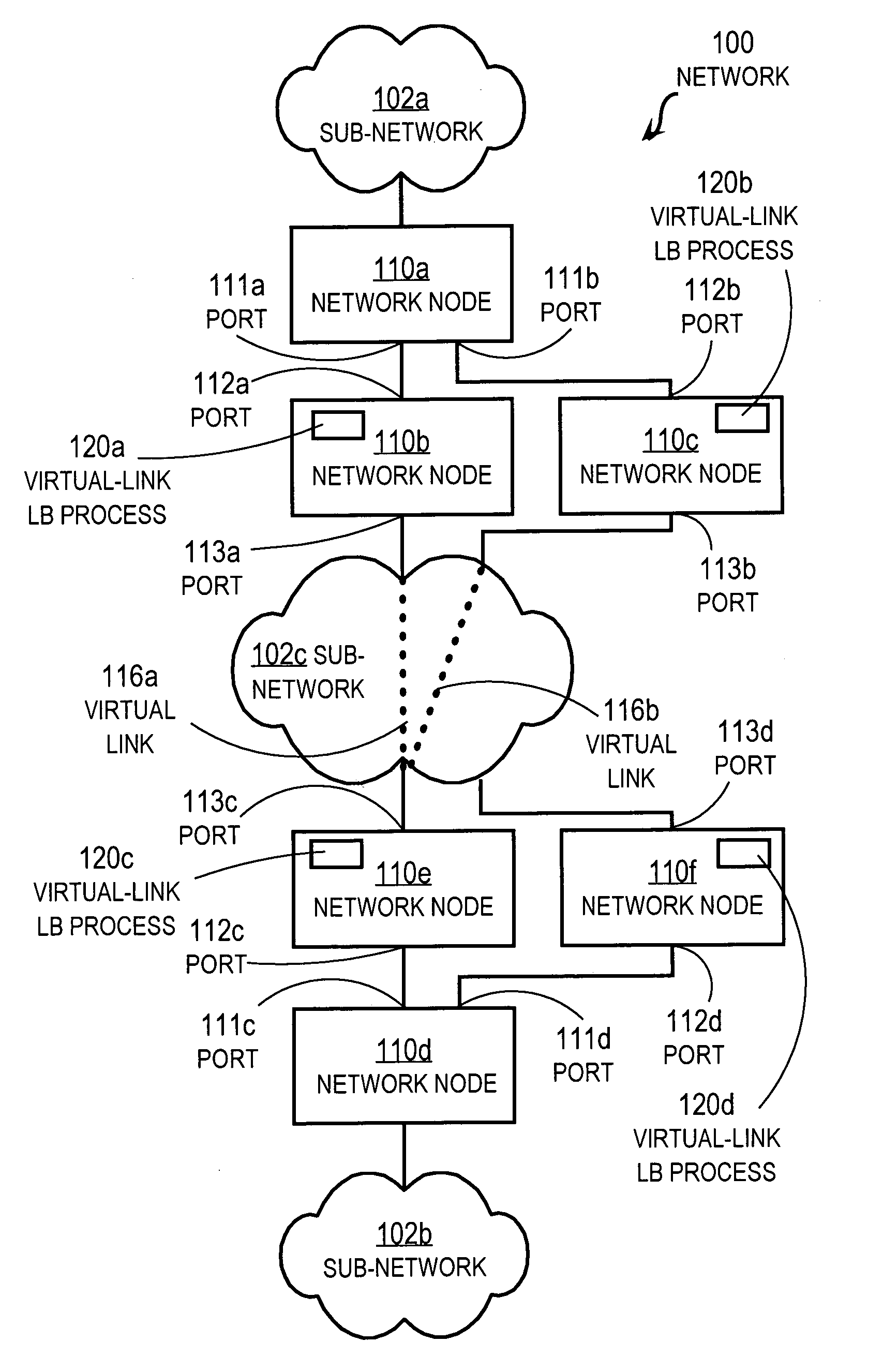
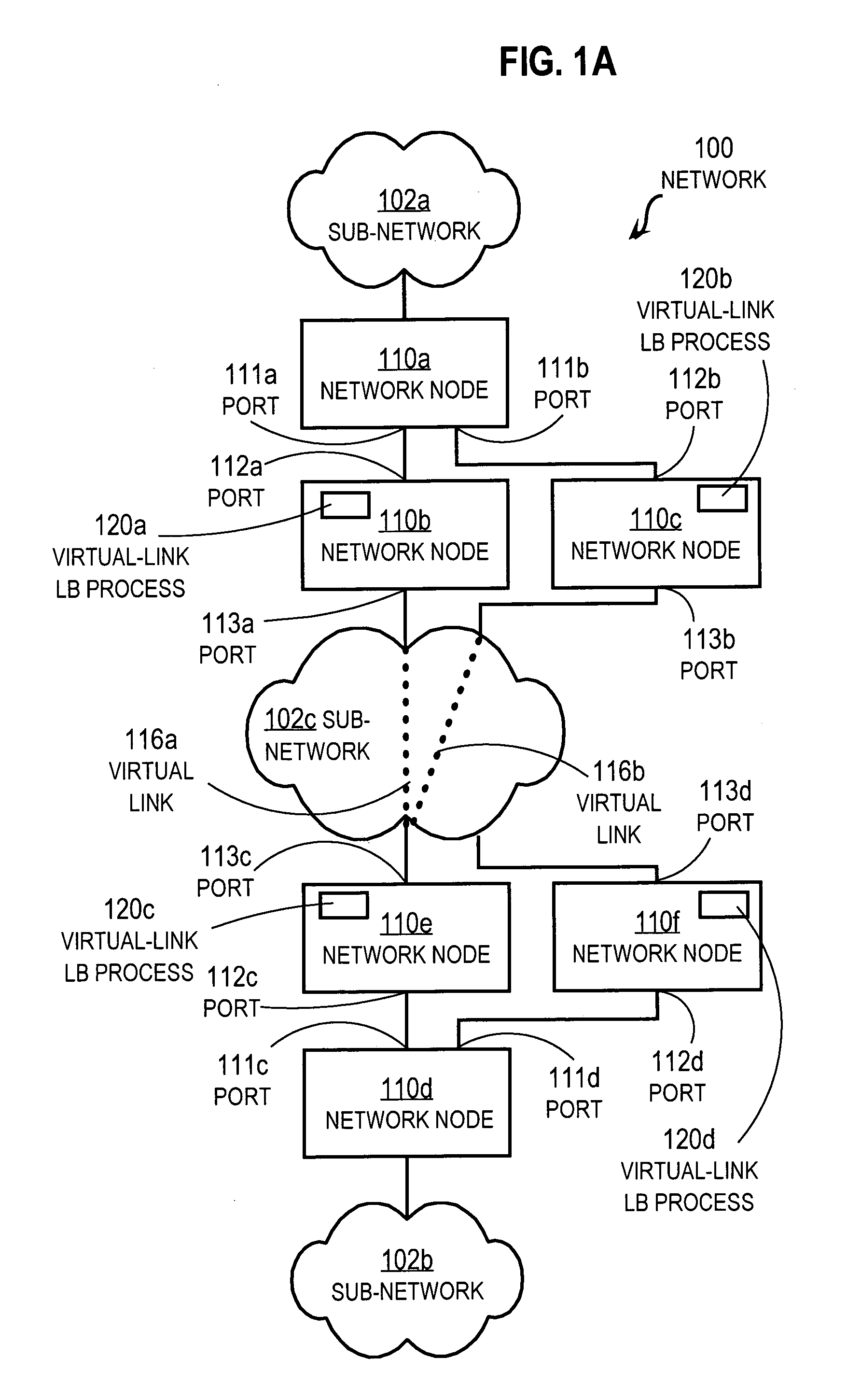
[0024]A method and apparatus are described for balancing of data packet traffic loads over a virtual link bundle in a network. In the following description, for the purposes of explanation, numerous specific details are set forth in order to provide a thorough understanding of the present invention. It will be apparent, however, to one skilled in the art that the present invention may be practiced without these specific details. In other instances, well-known structures and devices are shown in block diagram form in order to avoid unnecessarily obscuring the present invention.

[0025]The invention is described in the following sections in the context of load balancing layer 2 virtual links over an optical ring using RPR protocol to create loop-free virtual point-to-point links between pairs of provider edge nodes. However, the invention is not limited to this context. In other embodiments, different layer 2 virtual point-to-point links are bundled, such as links using MPLS, MAC-in-MAC...


PUM


Abstract

Techniques for load balancing network traffic over virtual point-to-point data links at a data-link layer include determining a particular group of virtual point-to-point data links that reach a particular local area network of one or more network nodes. A particular data-link address for a particular node of the particular local area network is associated with each virtual point-to-point data link of the particular group. When a data packet is received that includes data that indicates the particular data-link address as a destination; one virtual point-to-point data link of the group is determined to balance traffic among the group. The data packet is sent only over the one virtual point-to-point data link. These techniques enable virtual point-to-point data links through two or more intermediate network nodes, such as a pair of provider edge nodes, to be bundled for load balancing purposes.

Description

BACKGROUND OF THE INVENTION[0001]1. Field of the Invention[0002]The present invention relates to load balancing for networks with bundles of communication links between one network device and at least one pair of different network devices, such as a pair of provider edge nodes through which customer networks are connected to a provider network, such as a metropolitan area network (MAN).[0003]2. Description of the Related Art[0004]Networks of general purpose computer systems and special purpose devices connected by external communication links are well known and widely used in commerce. The networks often include one or more network devices that facilitate the passage of information between the computer systems and special purpose devices. A network node is a network device or computer system or other special purpose device connected by the communication links.[0005]Information is exchanged between network nodes according to one or more of many well known, new or still developing pro...

Claims


Application Information

Patent Timeline
Patent Type & Authority Applications(United States)
IPC IPC(8): H04L12/56
CPCH04L47/125H04L12/4641
Inventor ERVIN, JIMMYTAKEFMAN, MIKEBHAGWATULA, PRAVEENALEXANDER, JAMESFAULKNER, STEVEN
Owner CISCO TECH INC
Why Eureka
Try Eureka