Dispensing cap with center channel and helical flow profile

a technology of dispensing cap and center channel, which is applied in the direction of packaging, transportation and packaging, liquid transfer devices, etc., can solve the problems of more difficult manufacturing, more expensive than traditional one-piece dispensing cap, and squeezing of the container, so as to prevent spurting

Active Publication Date: 2008-03-06
WESTROCK SLATERSVILLE
View PDF48 Cites 15 Cited by
  • Summary
  • Abstract
  • Description
  • Claims
  • Application Information

AI Technical Summary

Benefits of technology

[0009]The present invention provides a one-piece dispensing closure having a unique internal flow structure that provides both a “clean pour” and a sufficient flow restriction to prevent spurting.

Problems solved by technology

Past dispensing closures tended to leak product onto the top deck of the closure after dispensing, creating a messy appearance and often requiring cleaning to reseal the closure.
While these silicone valves have been widely accepted by both the manufacturers and the consumers, they are somewhat more difficult to manufacture, as they require several inter-fitting parts, and thus they tend to be more expensive than traditional one-piece dispensing closures.
Another perceived drawback to the silicone valve closures is that they are constructed out of two different types of plastic and thus, from a recycling standpoint, they are more difficult to recycle because the silicone valve must be separated from the plastic closure body for recycling.
While this is not a major issue in the United States, at least yet, it is currently a major issue in Europe where recycling is extremely important and even mandated in some countries.

Method used


Image

  • Dispensing cap with center channel and helical flow profile
  • Dispensing cap with center channel and helical flow profile
  • Dispensing cap with center channel and helical flow profile

Examples


Embodiment Construction

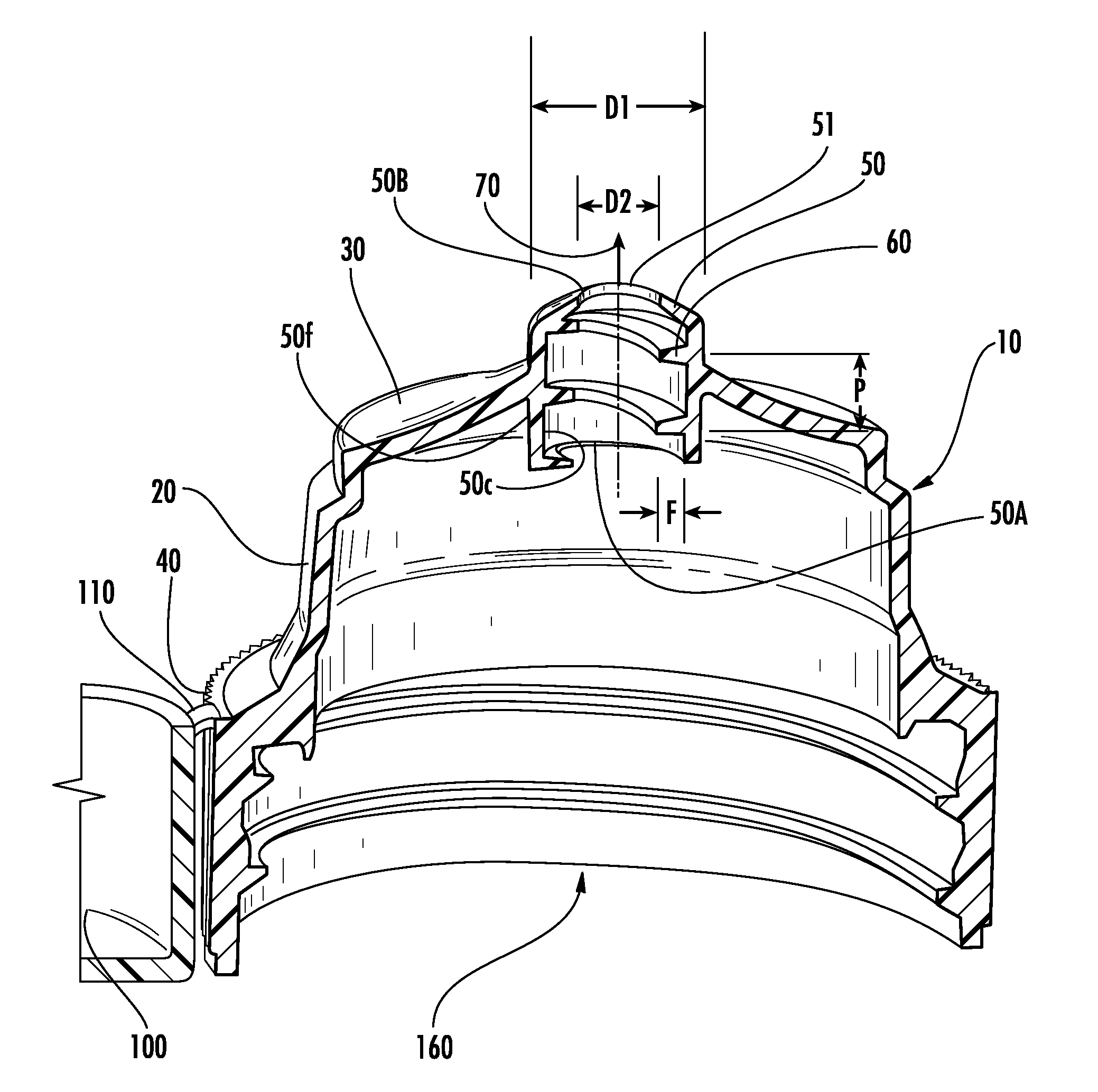
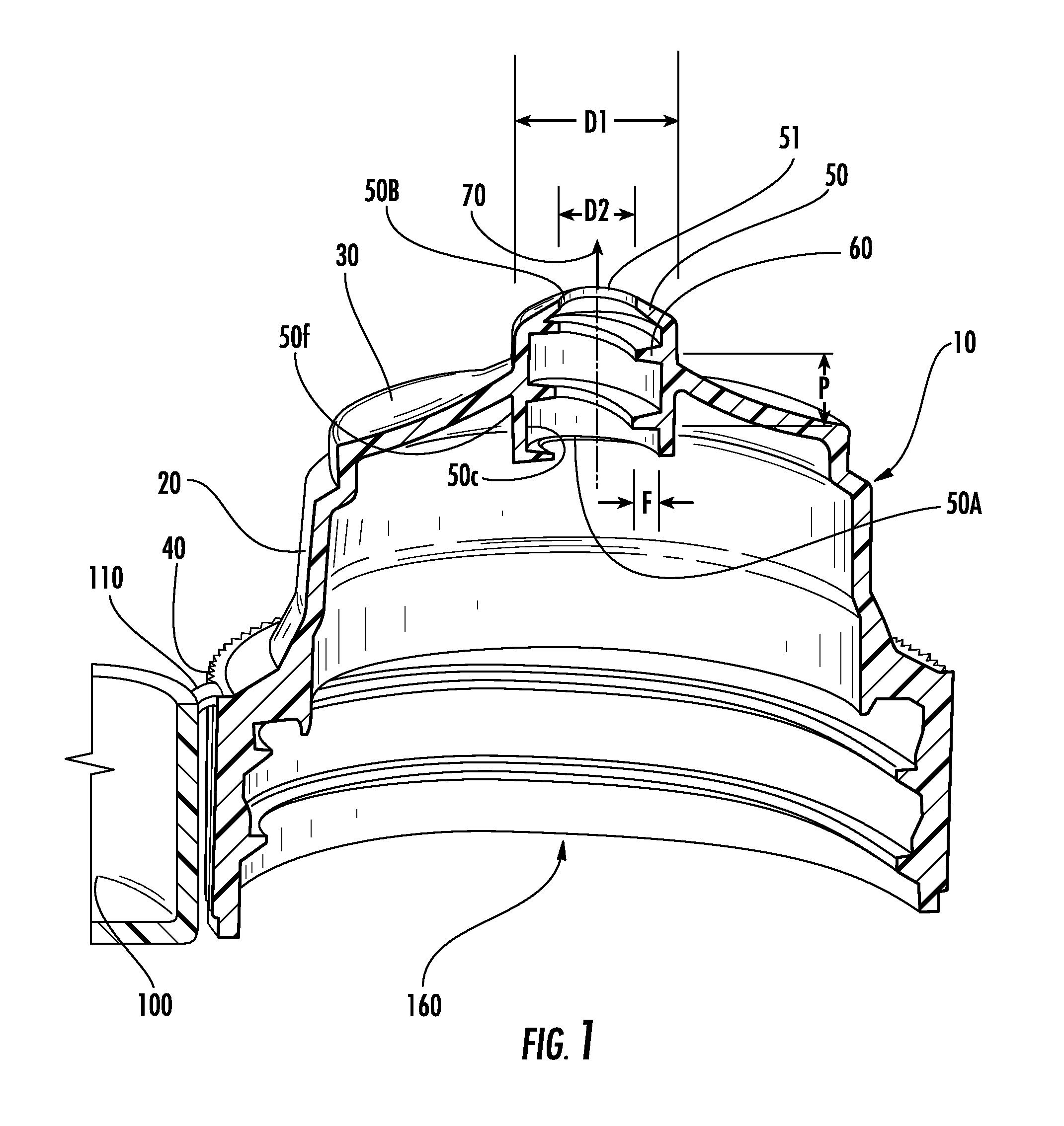
[0026]Referring now to the drawings, the dispensing closure of the instant invention is illustrated and generally indicated at 10 in FIGS. 1, and 3-6. As will hereinafter be more fully described, the instant dispensing closure 10 includes a unique flow conduit arrangement, which includes an unobstructed central flow path and a partially obstructed peripheral flow path. This unique arrangement provides both “anti-spurting” in inverted containers as well as “suck-back” for cleaner product dispensing, i.e. “clean-pour”.

[0027]Generally, each of the embodiments includes a closure body 20 having an upper deck 30, and a skirt 40 depending from the upper deck 30 where the skirt 40 is configured and arranged to mount to a product container (not shown), such as a conventional squeeze-type container. The skirt 40 is internally threaded for threaded mounting on a product container. However, it is to be understood that other skirt mounting arrangements are also contemplated within the scope of t...


PUM


Abstract

A dispensing closure for viscous fluids contains a closure body, a closure lid and a living hinge structure hingeably connecting the closure lid to the closure body. The closure body includes an upper deck, a skirt configured and arranged to mount to a product container, and a flow conduit extending through the upper deck to provide a flow path from an interior of the closure to an exterior of the closure. The flow conduit includes an entrance orifice and an exit orifice, and an inner wall extending between the entrance orifice and the exit orifice. To provide the desired flow effect, the inner wall includes at least one flow inhibitor structure, such as helically threaded flights extending at least partially inwardly from the inner wall into the flow path to define an unobstructed central flow path and a partially obstructed peripheral flow path.

Description

CROSS REFERENCE TO RELATED APPLICATION[0001]This application is related to and claims priority from earlier filed provisional patent application Ser. No. 60 / 824,322 filed Sep. 1, 2006 and incorporated herein by reference.BACKGROUND OF THE INVENTION[0002]The instant invention relates to container closures, and more particularly to squeeze-type container dispensing closures.[0003]There are two major trends occurring in the design of dispensing containers and closures. The first trend is a focus on providing a “clean pour” during dispensing of the product. Many food products, such as mustard and ketchup have a high viscosity and require the user to both tip and squeeze the container to dispense the product. Past dispensing closures tended to leak product onto the top deck of the closure after dispensing, creating a messy appearance and often requiring cleaning to reseal the closure. The current emphasis in “clean pour” design is on creating a “suck-back” effect as pressure is released ...

Claims


Application Information

Patent Timeline
Patent Type & Authority Applications(United States)
IPC IPC(8): B67D3/00
CPCB65D47/06
Inventor ROMANOV, SERGEYSKILLIN, CLIFFORDBRANNON, PATRICK J.
Owner WESTROCK SLATERSVILLE
Why Eureka
Try Eureka