Axial gap type motor

a gap type, axial gap technology, applied in the direction of dynamo-electric machines, magnetic circuit rotating parts, magnetic circuit shape/form/construction, etc., can solve the problems of limited practicable revolutions and torque, and achieve the effect of preventing the increase of permanent magnets in the rotor from excessively increasing

Inactive Publication Date: 2008-06-05
HONDA MOTOR CO LTD
View PDF3 Cites 46 Cited by
  • Summary
  • Abstract
  • Description
  • Claims
  • Application Information

AI Technical Summary

Benefits of technology

[0007]The present invention is achieved in view of the above-mentioned circumstances and has an object to provide an axial gap type motor in which an induced voltage constant can be varied while restraining an increase of a permanent magnetic required for a construction of a motor.
[0009]According to the axial gap type motor of the present invention, the state of the axial gap type motor can be set to a strong field in which a magnetic field is converged by an effect of a magnetic flux lens owing to the main magnets and the sub permanent magnets in a Halbach array or a weak field in which a short-circuit of magnetic paths are generated between the main magnets and the sub permanent magnets. Thus, magnetic flux linkage which links with a stator wire of the stators is increased or decreased by the magnetic field flux of the main magnets and the sub permanent magnets, so that the induced voltage constant is variable. As a result, a range of practicable revolutions and a range of torque of the axial gap type motor can be enlarged without increasing the permanent magnets constructing the rotor; therefore, driving efficiency can be improved and the operable range in high efficiency can be enlarged.
[0013]In this case, the effect of the magnetic flux lens owing to a Halbach array of the main permanent magnets and sub permanent magnets can be utilized effectively when the axial gap type motor is set to the strong field; alternately, the short-circuit of the magnetic path between the main permanent magnets and the sub permanent magnets can be utilized effectively when the axial gap type motor is set to the weak field. Therefore, magnetic flux linkage in which the main permanent magnets and the sub permanent magnets link the stator windings of the stators can be increased or decreased suitably; thus, variable range of the induced voltage constant can be enlarged.
[0017]In this case, since the plurality of main magnets are constructed by the electromagnets and the main permanent magnets, while preventing the permanent magnets constructing the rotor from increasing excessively, desired magnetic field flux can be maintained even if the current to the electromagnets becomes erratic.
[0019]In this case, the plurality of sub permanent magnets are arranged along the circumferential direction at regular intervals. Both of or one of a pair of the sub permanent magnets can be omitted, which are disposed between the main magnets adjacent to each other along the circumferential direction, and each of which is shifted to either side along the rotation axis. As a result, a desired magnetic field flux can be maintained while preventing the permanent magnets constructing the rotor from excessive increase.

Problems solved by technology

The above conventional permanent-magnet synchronous apparatus has a problem in which practicable revolutions and torque are limited to certain values by generation of prescribed back electromotive voltage in accordance with an induced voltage constant in high-revolution region since the induced voltage constant is a fixed value according to a construction of the rotor having the permanent magnet or the like.

Method used


Image

  • Axial gap type motor
  • Axial gap type motor
  • Axial gap type motor

Examples


Embodiment Construction

[0032]An embodiment of an axial gap type motor according to the present invention will be described with reference to the drawings.

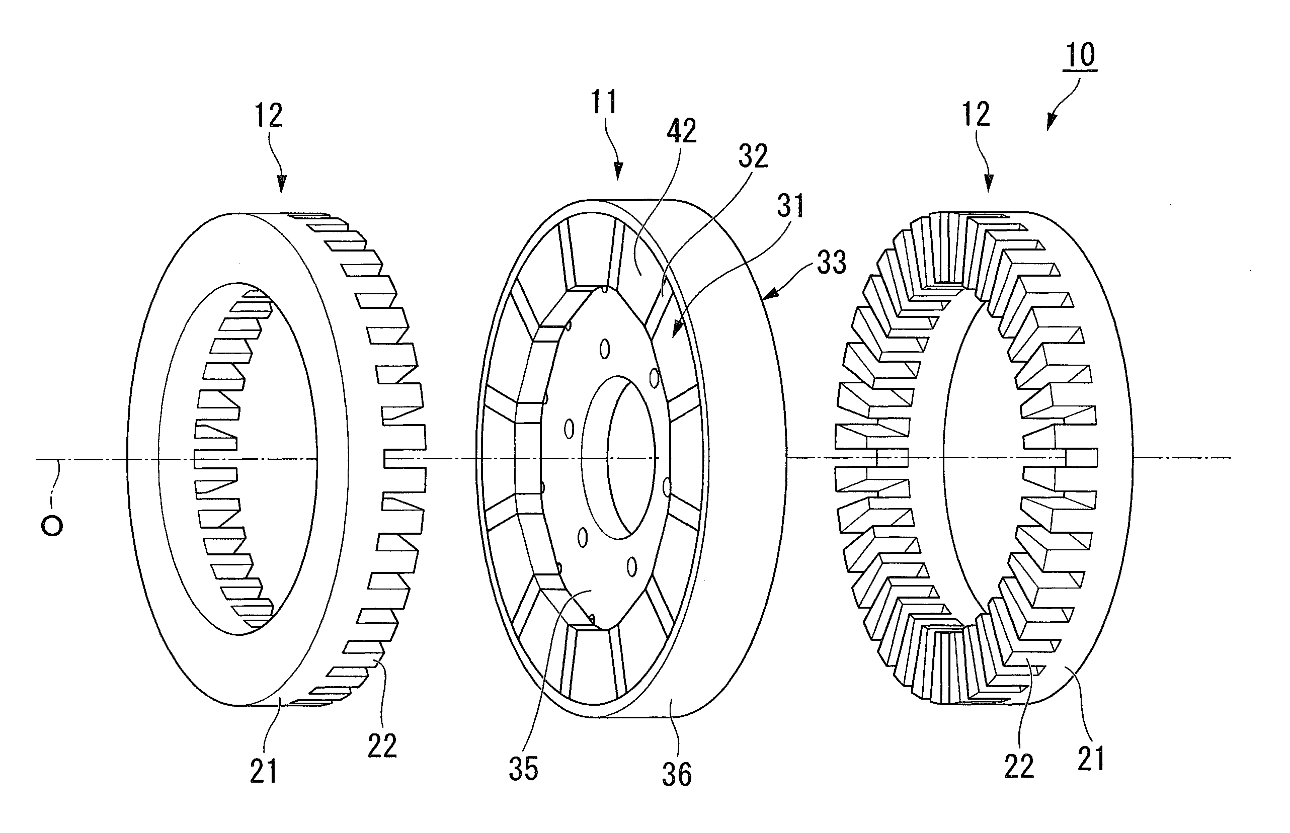
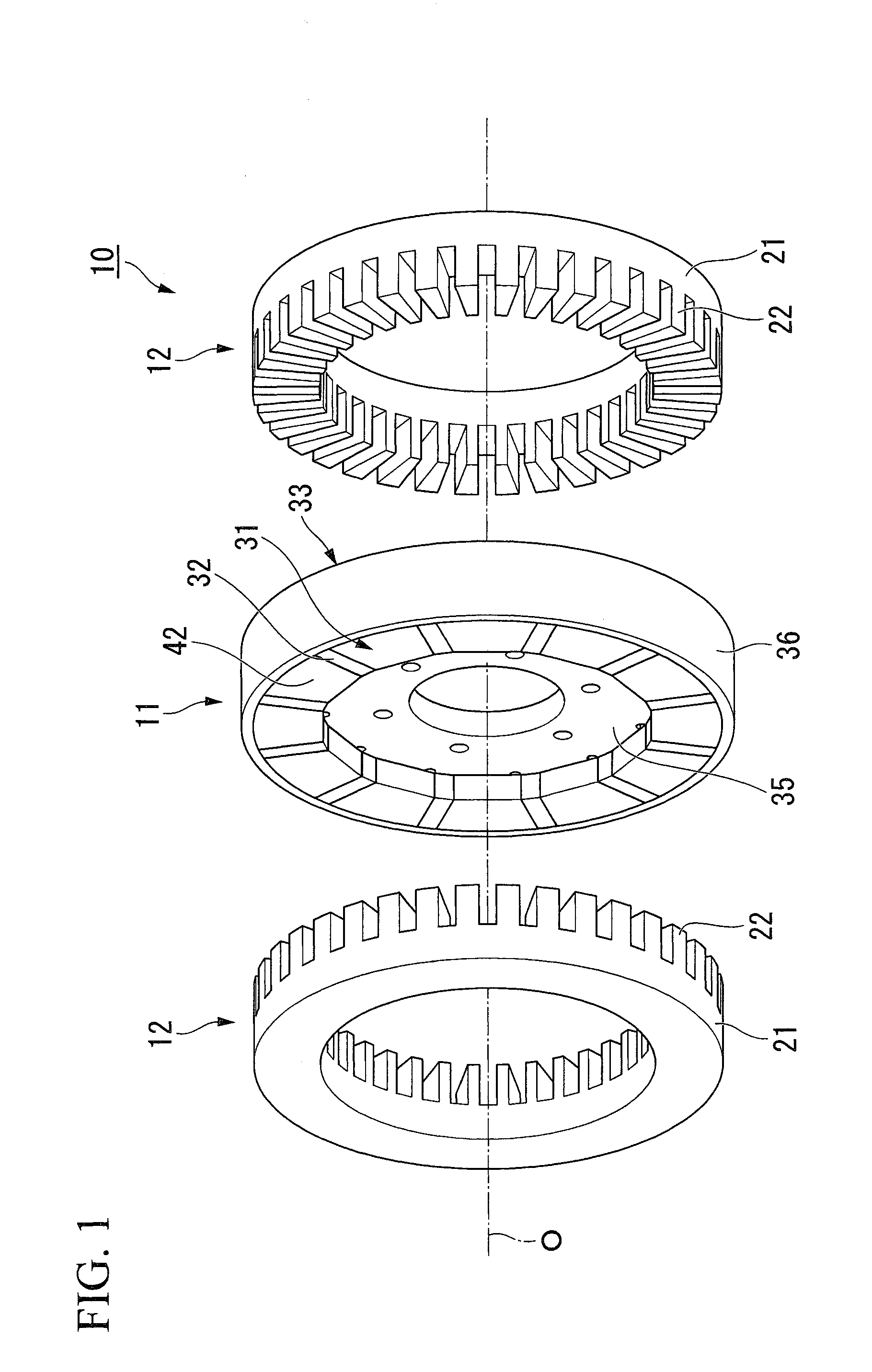
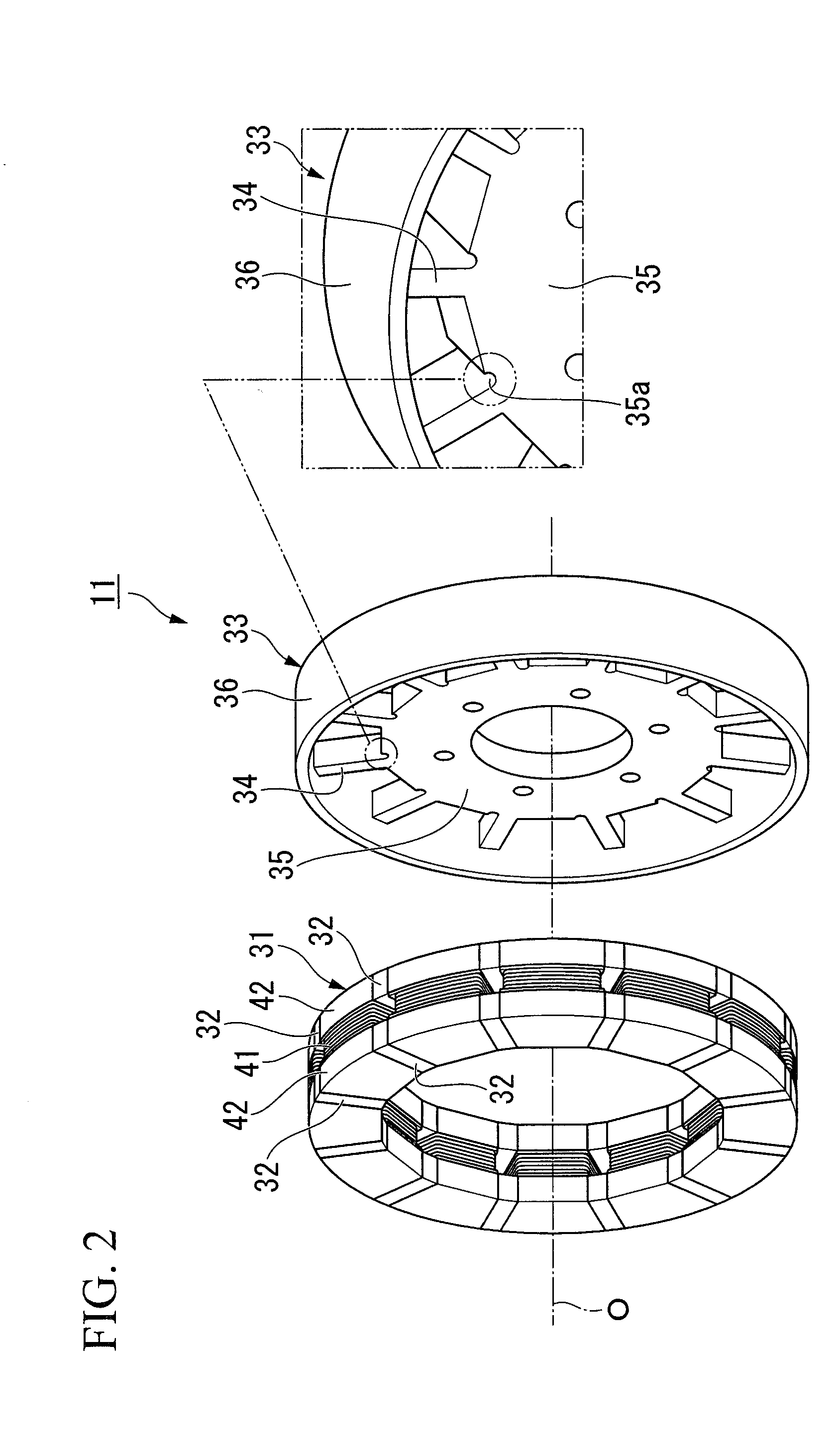
[0033]An axial gap type motor 10 of the present embodiment has, as shown in FIG. 1, a rotor 11 having substantially a circle-shape and being provided so as to be rotatable around a rotation axis O of the axial gap type motor 10, and a pair of stators 12 holding the rotor 11 therebetween from both sides along O, facing each other, and having stator windings of phases generating a rotating magnetic field rotating the rotor 11.

[0034]The axial gap type motor 10 is mounted on, for example, a vehicle such as a hybrid vehicle, a motor vehicle, and the like. The driving force of the axial gap type motor 10 is transmitted via a transmission (not illustrated) to driving wheels of the vehicle (not illustrated) by connecting an output shaft to an input shaft of the transmission.

[0035]the axial gap type motor 10 functions as a generator and generates regenerative bra...


PUM


Abstract

An axial gap type motor according to the present invention includes: a rotor; and a pair of stators which are arranged to face each other and hold the rotor from both sides thereof along a rotation axis. The rotor includes: electromagnets which are provided on the rotor as main magnets, and arranged along a circumferential direction so that directions of magnetic fluxes thereof are parallel to the rotation axis; and sub permanent magnets which are provided on the rotor, arranged in the vicinities of circumferential end portions of the main magnets, and are magnetized orthogonal to the rotation axis and a radial direction.

Description

BACKGROUND OF THE INVENTION[0001]1. Field of the Invention[0002]The present invention relates to an axial gap type motor.[0003]Priority is claimed on Japanese Patent Application No. 2006-325397, filed on Dec. 1, 2006, and Japanese Patent Application No. 2007-223053, filed on Aug. 29, 2007, the contents of which are incorporated herein by reference.[0004]2. Description of Related Art[0005]Conventionally, an axial gap type permanent-magnet synchronous apparatus having a rotor and a pair of stators opposed to each other and holding the rotor therebetween from both sides of a rotation axis is known. In the permanent-magnet synchronous apparatus, a magnetic flux loop is formed via the pair of stators with respect to a magnetic field flux by a permanent magnet of the rotor (refer to Japanese Unexamined Patent Application, First Publication No. H10-271784, and Japanese Unexamined Patent Application, First Publication No. 2001-136721, for example).[0006]The above conventional permanent-magn...

Claims


Application Information

Patent Timeline
Patent Type & Authority Applications(United States)
IPC IPC(8): H02K16/04H02K21/00
CPCH02K16/04H02K21/042H02K21/04
Inventor ABE, SHOEIATARASHI, HIROFUMIYAMAMOTO, KEIICHITAJIMA, SHIGERUKAWAKAMI, MAKOTOFUKUDA, TAKEO
Owner HONDA MOTOR CO LTD
Why Eureka
Try Eureka