Strip illumination device

a technology of led-based illumination and strip luminaire, which is applied in the direction of semiconductor devices for light sources, lighting and heating apparatus, lighting support devices, etc., can solve the problems of difficult installation and service of strip luminaires, led-based devices often not conducive to customized installations, and leds tend to decrease both in brightness and expected lifetime, so as to facilitate customized installation and efficiently direct heat away from leds

Inactive Publication Date: 2008-08-14
DIAMOND CREEK CAPITAL LLC
View PDF70 Cites 108 Cited by
  • Summary
  • Abstract
  • Description
  • Claims
  • Application Information

AI Technical Summary

Benefits of technology

[0007]Accordingly, there is a need in the art for a low-profile, LED-based strip illumination device that is easy to adapt to customized installations. There is also a need for an LED-based strip illumination device that efficiently directs heat away from the LED.

Problems solved by technology

Also, due the their typical positioning, for example as under-cabinet lighting or cove lighting, strip luminaires may be difficult to install and service.
However, such LED-based devices often are not conducive to customized installations, in which the length of a prefabricated strip may need to be adjusted during installation.
Also, LEDs tend to decrease both in brightness and in expected lifetime if they operate in configurations in which the heat generated by the LED is not efficiently evacuated.

Method used


Image

  • Strip illumination device
  • Strip illumination device
  • Strip illumination device

Examples


Embodiment Construction

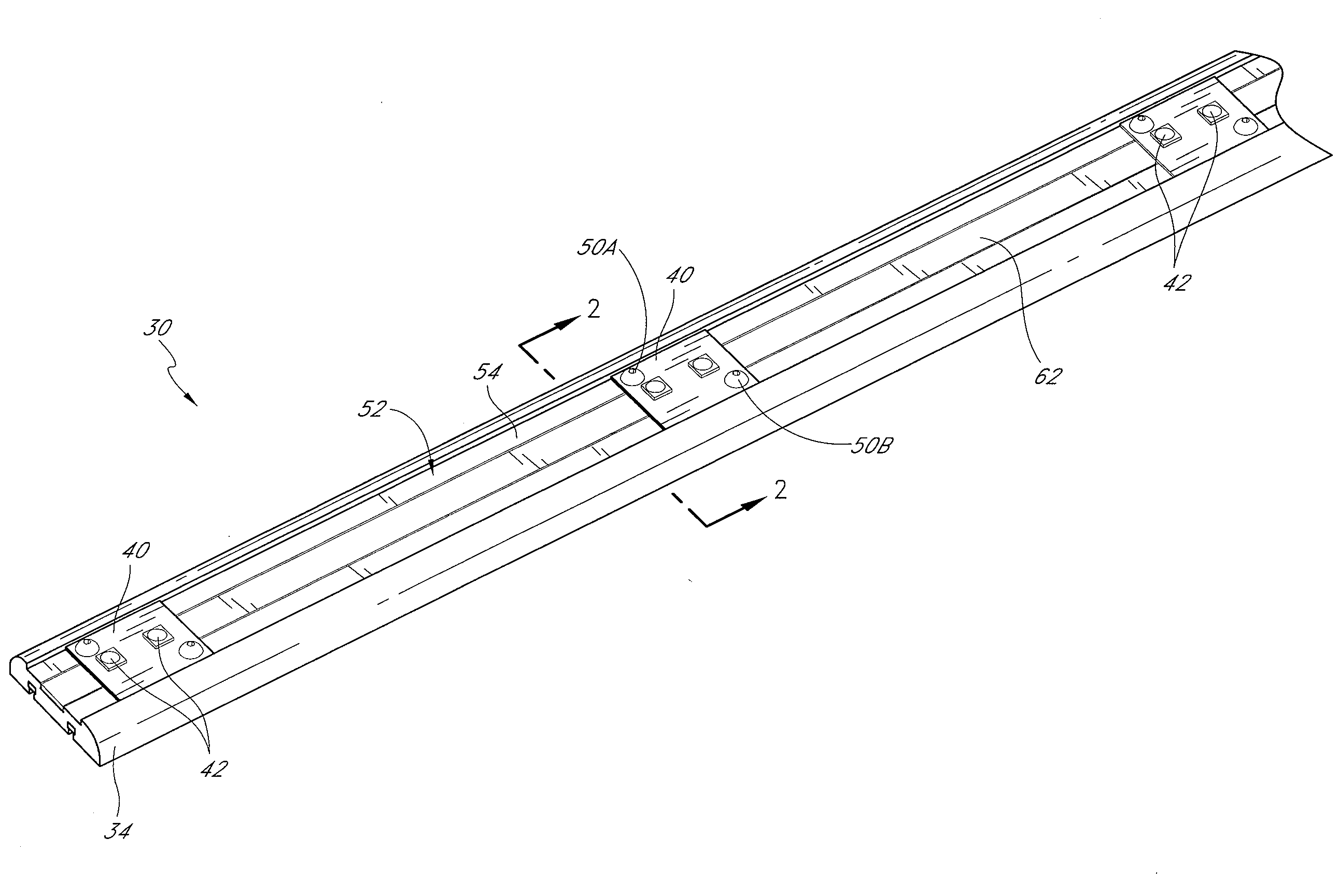
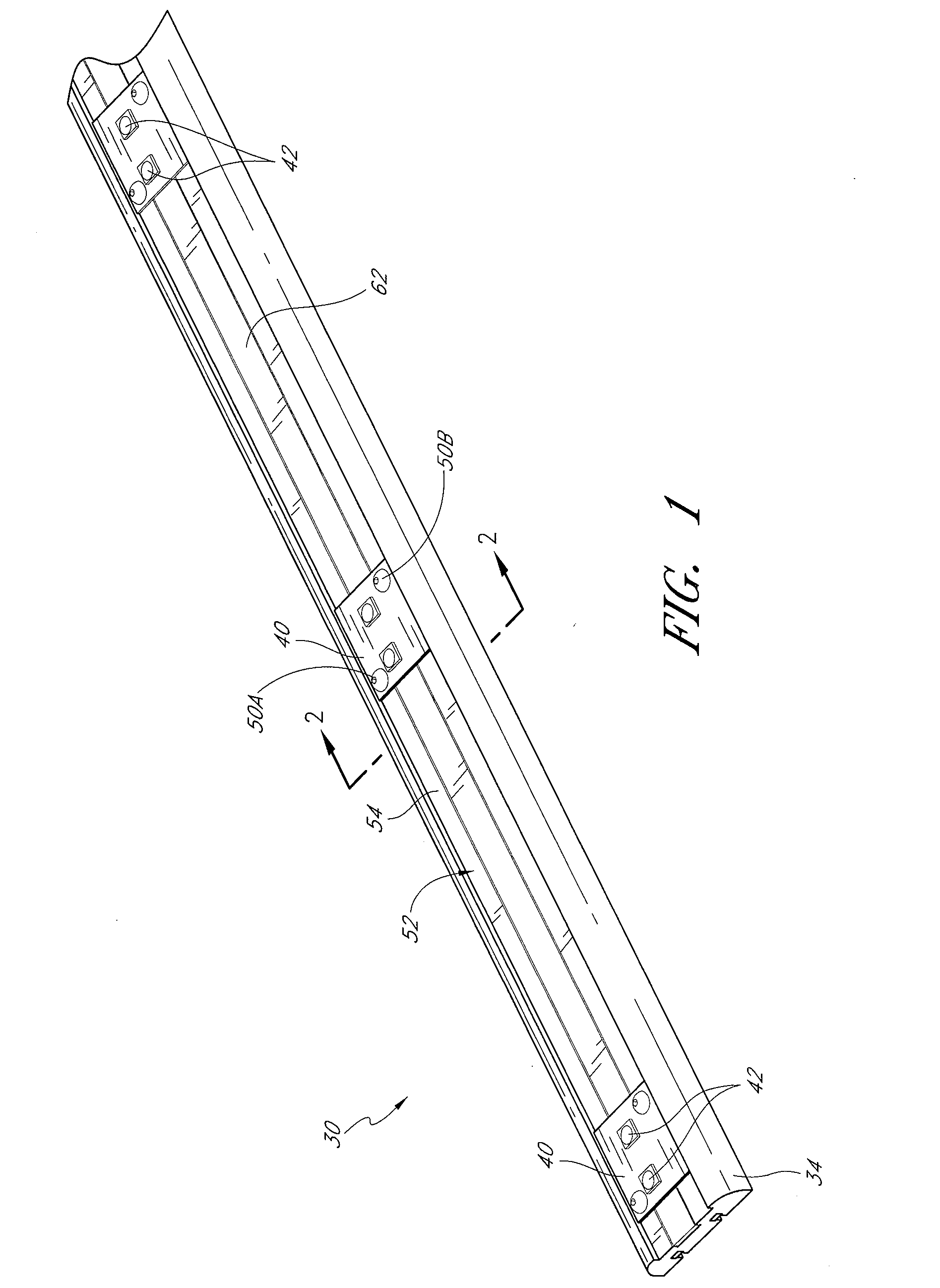
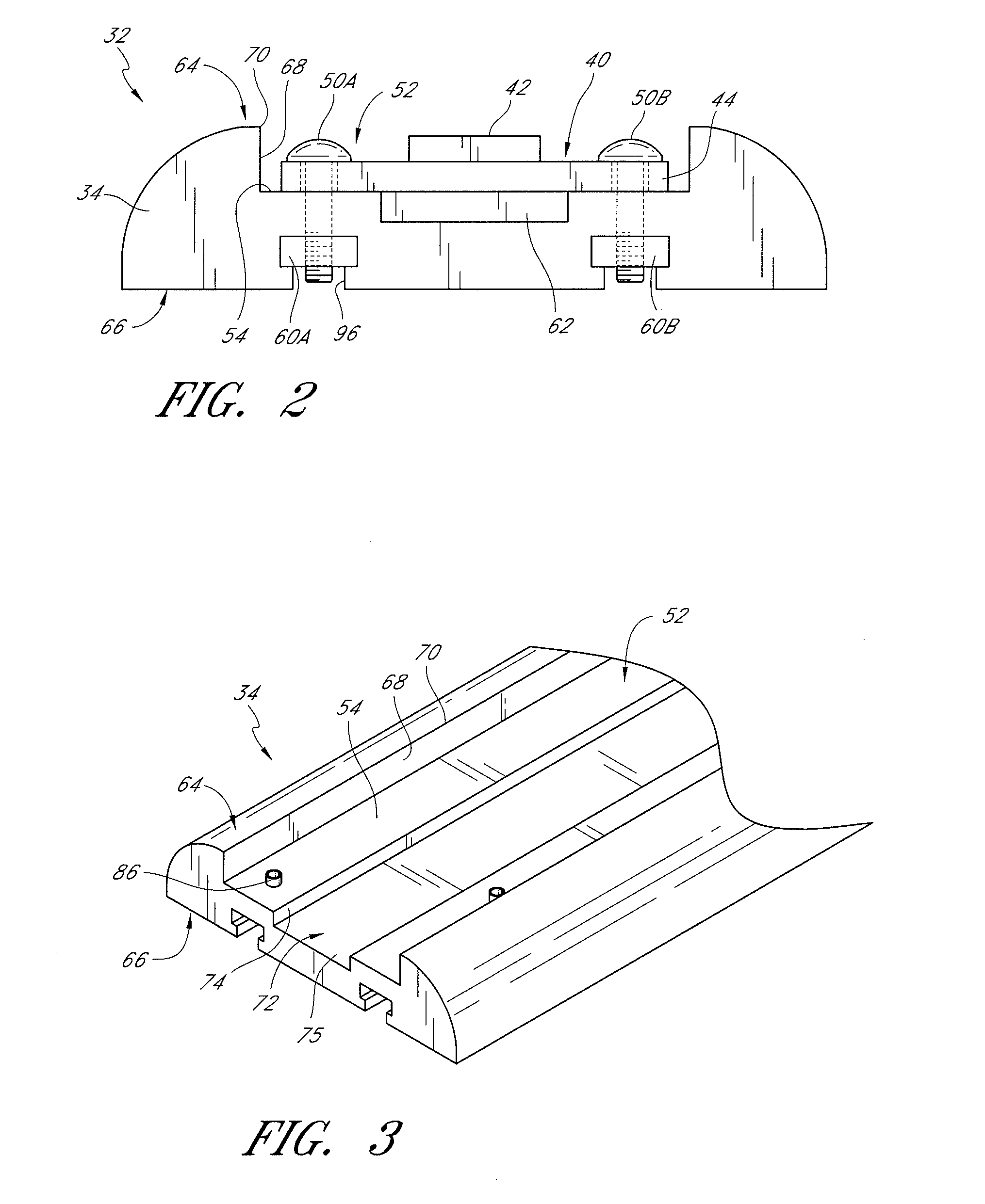
[0027]With initial reference to FIGS. 1-6, an embodiment of a strip illumination device 30 is presented. Such a device comprises a light strip section 32 that can be used alone, trimmed to a desired size, and / or combined with other sections to create an illumination system.

[0028]In the illustrated embodiment the strip section 32 comprises an elongate substrate 34 upon which a plurality of light emitting diode (LED) modules 40 are mounted spaced apart from each other. Each LED module 40 comprises one or more LEDs 42 that provide light when energized. The illustrated embodiment includes modules 40 having two LEDs 42. Preferably, the LED modules 40 have an easily-mounted and thermally managed structure such as is disclosed in assignee's U.S. Pat. No. 7,114,831, the entirety of which is hereby incorporated by reference. For example, the LED module 40 preferably has a heat conductive body 44, such as an aluminum body, upon which an electric circuit 46 is disposed. Preferably, the circuit...


PUM


Abstract

A low-profile strip illumination device comprises a substrate supporting an elongate heat conductor and positively and negatively energized elongate rails. A plurality of spaced apart light emitting diodes (LEDs) are mounted so as to be powered by the elongate rails. The LEDs are arranged generally adjacent the elongate heat conductor so that a heat flow path is defined from each LED to the elongate heat conductor and to the environment.

Description

CROSS-REFERENCE TO RELATED APPLICATIONS[0001]This application claims the benefit of U.S. Provisional Application No. 60 / 901,138, which was filed on Feb. 14, 2007, the entirety of which is hereby incorporated by reference.BACKGROUND[0002]1. Field of the Invention[0003]The present invention is in the field of illumination devices and, more specifically, light emitting diode (LED)-based illumination devices.[0004]2. Description of the Related Art[0005]Strip-type illumination devices are particularly useful for lighting applications such as under-cabinet lighting and cove lighting. Such strip illumination devices are typically made up of a plurality of light sources spaced apart from one another along a length of an elongate substrate. Generally, it is desirable to hide such strip illumination devices from direct view. Thus, manufacturers try to design strip devices having a comparably low profile as compared to other luminaires. Also, due the their typical positioning, for example as u...

Claims


Application Information

Patent Timeline
Patent Type & Authority Applications(United States)
IPC IPC(8): F21S4/00F21V29/00
CPCF21S4/008F21V19/0055F21V29/004F21V29/74F21Y2101/02Y10S362/80F21V33/0012F21S4/28F21Y2115/10
Inventor STEEDLY, JAMESLYNCH, FERNANDOWERNER, CHRIS
Owner DIAMOND CREEK CAPITAL LLC
Why Eureka
Try Eureka