Stent

Inactive Publication Date: 2008-11-06
BOSTON SCI SCIMED INC
View PDF16 Cites 30 Cited by
  • Summary
  • Abstract
  • Description
  • Claims
  • Application Information

AI Technical Summary

Problems solved by technology

Many prior art stents however are not wholly satisfactory for use where the site of desired application of the stent is juxtaposed or extends

Method used


Image

  • Stent
  • Stent
  • Stent

Examples


Embodiment Construction

[0021]While this invention may be embodied in many different forms, there are described in detail herein specific embodiments of the invention. This description is an exemplification of the principles of the invention and is not intended to limit the invention to the particular embodiments illustrated.

[0022]For the purposes of this disclosure, like reference numerals in the figures shall refer to like features unless otherwise indicated.

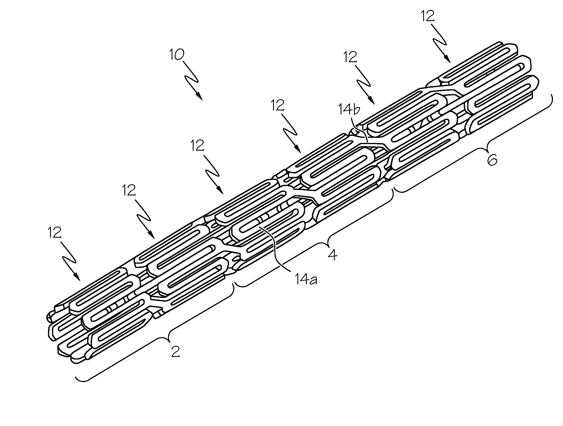
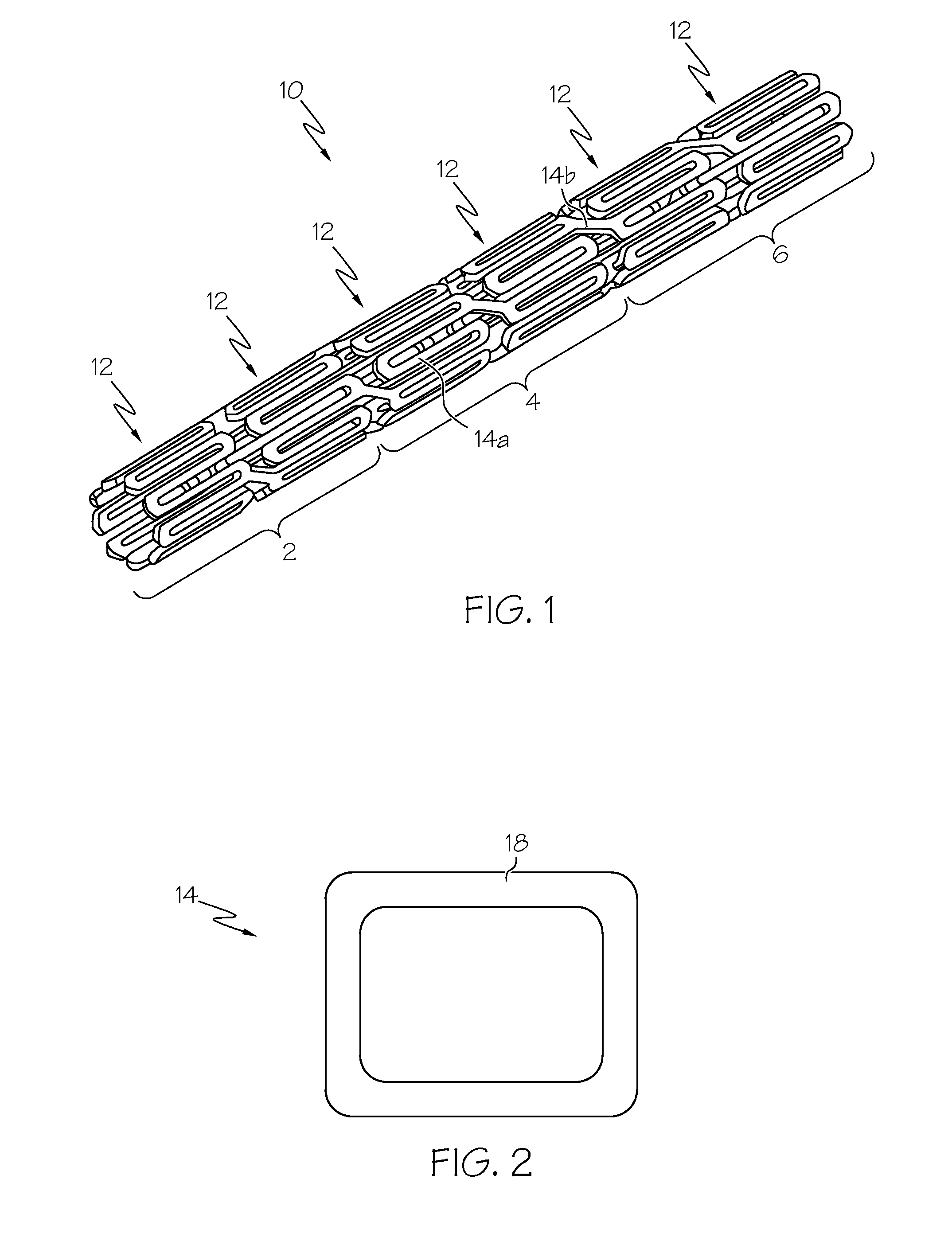
[0023]FIG. 1 depicts a stent 10 comprising a plurality of members 14 that form circumferential rings 11 extending about the circumference of the stent 10. As used in this application, members 14 include struts 14a and connectors 14b. The stent 10 illustrated in FIG. 1 is presented as an example of a configuration for a stent 10, as the present invention may be used with any stent 10 configuration desired. It is also within the scope of the invention for the stent 10 to have a braided tubular wall formed from at least two members. In this embodiment, ...


PUM


Abstract

In at least one embodiment, the invention is directed to mechanisms that affect the elution rate of a therapeutic agent that has been deposited on the surface of at least a portion of a stent. Mechanisms include grooves formed in the therapeutic agent that is coating at least a portion of the surface of the stent.
In at least one embodiment, the invention is directed to the directional release of a therapeutic agent contained within a reservoir formed in at least one member of a stent.

Description

CROSS-REFERENCE TO RELATED APPLICATIONS[0001]Not ApplicableSTATEMENT REGARDING FEDERALLY SPONSORED RESEARCH[0002]Not ApplicableBACKGROUND OF THE INVENTION[0003]A stent is a medical device introduced to a body lumen and is well known in the art. Typically, a stent is implanted in a blood vessel at the site of a stenosis or aneurysm endoluminally, i.e. by so-called “minimally invasive techniques” in which the stent in a radially reduced configuration, optionally restrained in a radially compressed configuration by a sheath and / or catheter, is delivered by a stent delivery system or “introducer” to the site where it is required. The introducer may enter the body from an access location outside the body, such as through the patient's skin, or by a “cut down” technique in which the entry blood vessel is exposed by minor surgical means.[0004]Stents, grafts, stent-grafts, vena cava filters, expandable frameworks, and similar implantable medical devices are radially expandable endoprosthese...

Claims


Application Information

Patent Timeline
IPC IPC(8): A61F2/82
CPCA61F2/91A61F2/915A61F2002/91541A61F2250/003A61F2250/0068
Inventor LENZ, JASON T.KOKATE, JAYKEEP Y.MILLER, MATTHEW J.
Owner BOSTON SCI SCIMED INC
Why Eureka
Try Eureka