Liquid discharging method and liquid discharging apparatus

a liquid discharging and liquid discharging technology, applied in the direction of printing, other printing apparatus, etc., can solve the problems of affecting the accuracy of the recording, the deterioration of recording quality and patterning precision, and the inability to describe the peak level and abrupt gradient, etc., to achieve the effect of preventing and restricting satellites

Inactive Publication Date: 2008-11-27
CANON KK
View PDF3 Cites 4 Cited by
  • Summary
  • Abstract
  • Description
  • Claims
  • Application Information

AI Technical Summary

Benefits of technology

[0015]In liquid discharging apparatus having the above-described configuration, the liquid discharging head is driven according to the volume variation so that the liquid column before and after separating the liquid droplet (main droplet) is gradually thickened toward the discharge port, and the liquid protrudes from the discharge port after separating the liquid droplet. Accordingly, it is possible to effectively prevent the liquid column from further being separated after the main droplet separation and to restrict the satellite from being generated.

Problems solved by technology

Accordingly, the satellite may be deposited at a position deviated from the main droplet in the liquid receptor such as the recording medium, which may cause deterioration of recording quality and patterning precision.
Additionally, the satellite may float in the form of a mist, and may be attached to an discharge port formation surface of the liquid discharging head, by which a direction of the liquid to be subsequently discharged may be diffracted or attached to the inside of the apparatus, which may cause contamination of the apparatus.
However, there is no detailed description about how the peak level is set and how the abrupt gradient of each region of the driving voltage waveform is estimated.

Method used


Image

  • Liquid discharging method and liquid discharging apparatus
  • Liquid discharging method and liquid discharging apparatus
  • Liquid discharging method and liquid discharging apparatus

Examples


example 1

3.1 Example 1

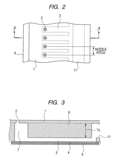
[0053]First, a liquid discharging head shown in FIGS. 2 and 3 was manufactured. At this time, an discharge port was configured as a round hole with a diameter of 30 μm, the length (a dimension in a horizontal direction in FIG. 3) of the individual liquid chamber 3 was set to 6,000 μm, and the width (a dimension in a direction perpendicular to the drawing in FIG. 3) thereof was set to 100 μm. In addition, the thickness of the actuator 5 was 3 μm and the thickness of the diaphragm 4 was 6 μm.

[0054]Additionally, the liquid discharging head increases or decreases the volume of the individual liquid chamber according to a displacement (the out-of-plane displacement) of the diaphragm fixed to the piezoelectric element in a direction perpendicular to the surface thereof using the deformation of the piezoelectric element as the actuator. In such a liquid discharging head, the volume (control liquid amount VCON) of a flowing liquid at the time the diaphragm 4 displaces is determ...


PUM


Abstract

A liquid discharging head is appropriately driven to effectively prevent a satellite from being generated irrespective of conditions such as a property of a discharge liquid or a head structure. The liquid discharging head is driven using volume variation in a manner that a liquid extending in a column shape at the time of separating a liquid droplet (main droplet) is gradually thickened from the separation portion to an discharge port, and that the liquid protrudes from the discharge port during a period where the length of the liquid extending in the column shape is shortened after the droplet is separated. Accordingly, it is possible to effectively prevent a liquid column from further being separated after the main droplet is separated, and to restrict the satellite from being generated, irrespective of conditions such as the property of the discharge liquid or the head structure.

Description

BACKGROUND OF THE INVENTION[0001]1. Field of the Invention[0002]The present invention relates to a liquid discharging method and a liquid discharging apparatus and particularly those using a liquid discharging head including a discharge port for discharging a liquid and an individual liquid chamber which communicates with the discharge port and discharges the liquid from the discharge port according to volume variation. The invention is applicable to an apparatus for performing a recording operation on a recording medium such as a paper sheet, cloth, leather, non-woven, or an OHP plastic film, an apparatus for performing a patterning or processing operation on a medium (receptor) such as a substrate, plate material, or a solid material by attaching the liquid thereto, and a coating apparatus.[0003]2. Description of the Related Art[0004]There is a known liquid discharging head in which a diaphragm contacting a liquid in an individual liquid chamber is provided, the diaphragm is displ...

Claims


Application Information

Patent Timeline
IPC IPC(8): B41J2/165
CPCB41J2/04516B41J2/04581B41J2/04588
InventorKITAKAMI, KOICHISUMIYA, TOSHIHARU
OwnerCANON KK