Bicycle damper

a technology for dampers and bicycles, applied in the direction of shock absorbers, springs/dampers, functional characteristics of springs/dampers, etc., can solve the problems of shock absorbers and drastically reduce the efficiency of bicycles

Inactive Publication Date: 2009-01-01
SPECIALIZED BICYCLE COMPONENTS INC
View PDF18 Cites 16 Cited by
  • Summary
  • Abstract
  • Description
  • Claims
  • Application Information

AI Technical Summary

Benefits of technology

[0016]An aspect of one embodiment is a shock absorber for a bicycle comprising a primary tube comprising a compression chamber and a spring chamber, a piston rod that supports a main piston, a remote tube that is separate from the primary tube, an inertial valve within the remote tube, a shaft within the remote tube defining a plurality of flow ports and an outer annular groove connecting the plurality of flow ports, and a flow path connecting the remote fluid chamber and the compression chamber of the primary tube. The main piston is movable within the compression chamber of the primary tube. The remote tube comprises a remote fluid chamber. The inertial valve is responsive to terrain-induced forces and not responsive to rider-induced forces when the shock absorber is assembled to the bicycle. The inertia valve has an open position and a closed position. The inertial valve permits a flow of the fluid from the compression chamber of the primary tube to the remote fluid chamber of the remote tube when the inertial valve is open and the flow through the inertia valve is reduced when the inertia valve is in the closed position.

Problems solved by technology

However, an undesirable consequence of incorporating a suspension assembly in a bicycle is the tendency for the shock absorber to absorb a portion of the power output of a rider of the bicycle.
In some instances, i.e. when the rider is standing, the proportion of power absorbed by the shock absorber may be substantial and may drastically reduce the efficiency of the bicycle.
Typically, this will occur when the bicycle hits a severe bump.

Method used


Image

  • Bicycle damper
  • Bicycle damper
  • Bicycle damper

Examples


Embodiment Construction

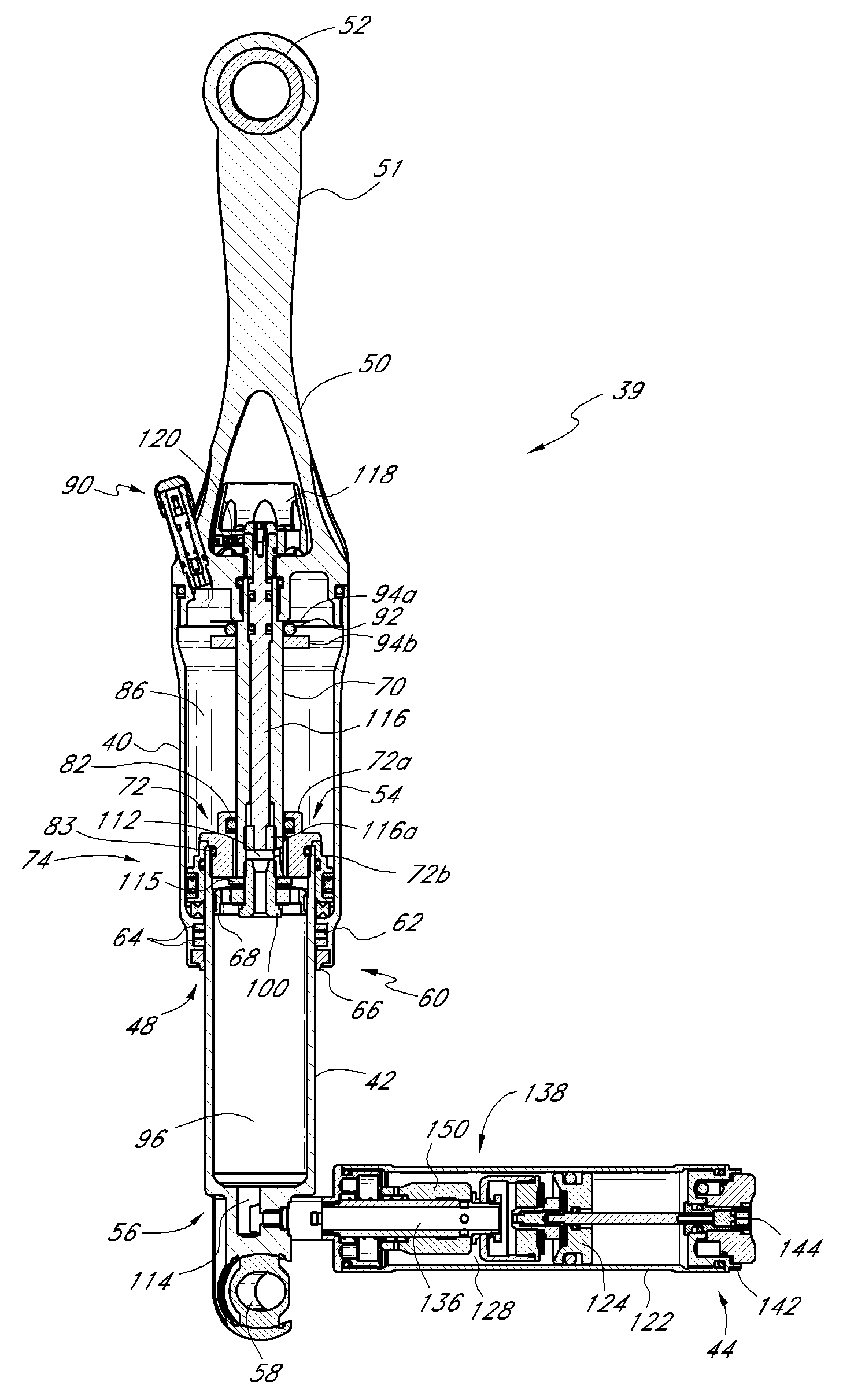
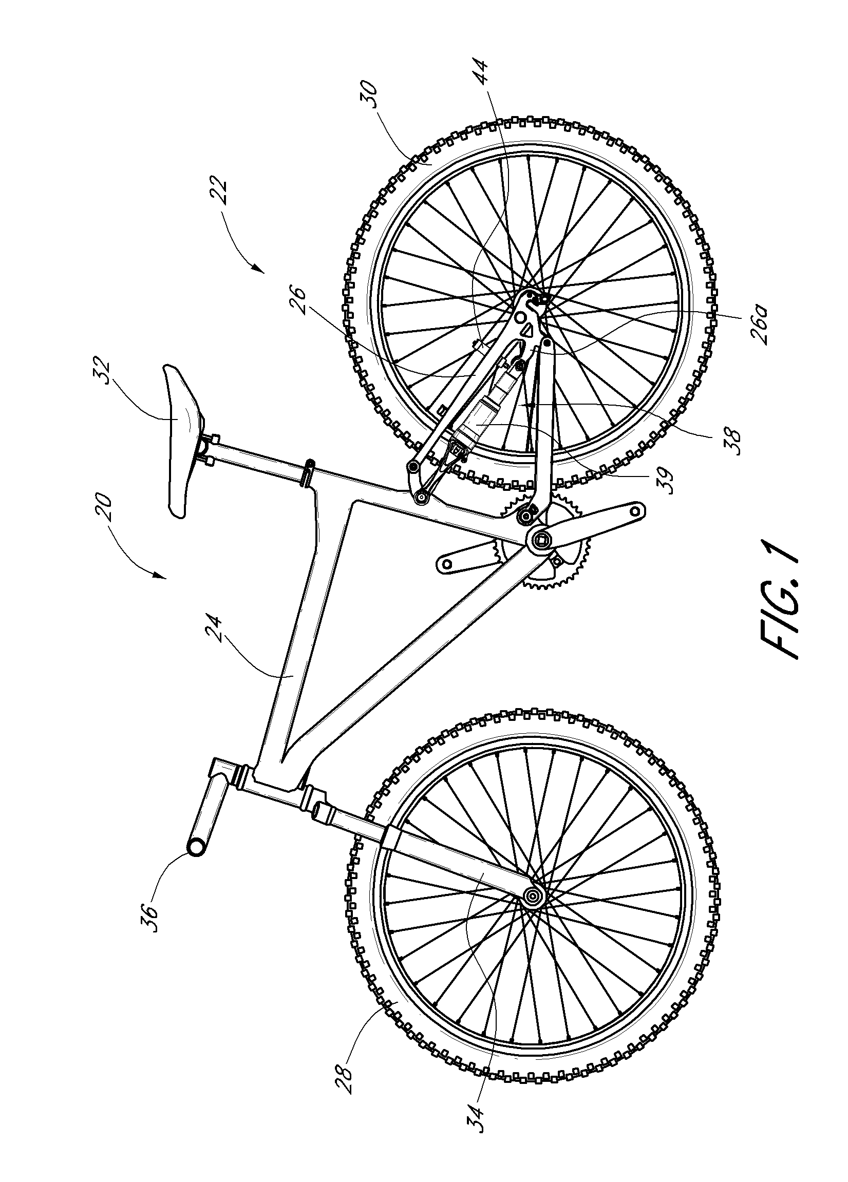
[0035]Referring to FIG. 1, a bicycle 20 (e.g., a mountain bike) having a preferred embodiment of a rear suspension assembly, or shock absorber, is illustrated. The bicycle 20 includes a frame 22, preferably comprised of a generally triangular main frame portion 24 and an articulating frame portion, or subframe 26, which is preferably pivotally connected to the seat post tube 25 of the main frame portion 24. The bicycle 20 also includes a front wheel 28 and rear wheel 30. The rear wheel 30 is connected to the subframe portion 26. A seat 32, to provide support to a rider in a sitting position, is connected to the seat post tube 25. It is understood that in some embodiments, main frame portion 24 may not be generally triangular or have a seat tube which extends uninterrupted to the bottom bracket.

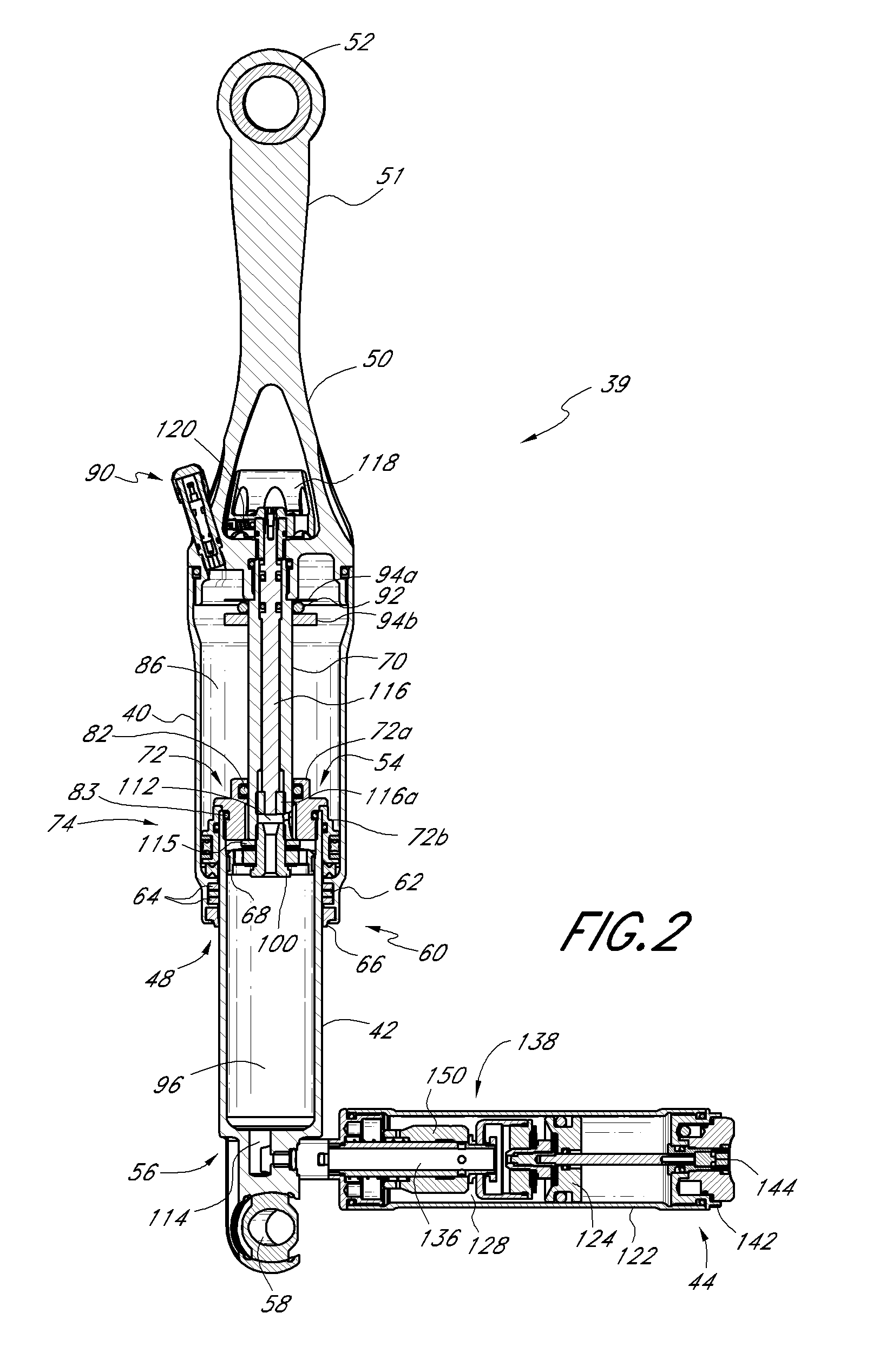
[0036]Positioned between the subframe 26 and the seat post tube 25 is a preferred embodiment of a rear shock 38. It is noted that, while the shock 38 disclosed herein is described in the conte...


PUM


Abstract

A damper for a bicycle, having a primary unit including a damper tube, a piston rod that supports a main piston, a reservoir tube that is outside of the compression chamber of the primary tube, and an inertial valve within the reservoir tube. The damper also includes a flow path connecting the reservoir fluid chamber and the compression chamber of the primary tube. The damper also may have a damping valve in the reservoir tube. When the inertia valve is open, the damping valve opens before flow through the inertia valve is maximized. The main piston and the damper tube at least partially define a compression chamber and a rebound chamber. The main piston is movable within the damper chamber of the primary unit. The reservoir tube includes a reservoir fluid chamber. The inertial valve is responsive to terrain-induced forces and not responsive to rider-induced forces when the shock absorber is assembled to the bicycle.

Description

CROSS-REFERENCE TO RELATED APPLICATIONS[0001]This application is related to, and claims priority from, U.S. Utility patent application Ser. No. 11 / 500,036, filed Aug. 7, 2006.INCORPORATION BY REFERENCE[0002]The entirety of U.S. Utility patent application Ser. No. 11 / 500,036, filed Aug. 7, 2006, is expressly incorporated by reference herein and made a part of the present specification.BACKGROUND OF THE INVENTION[0003]1. Field of the Invention[0004]The present invention generally relates to vehicle suspension systems. More specifically, the present invention relates to an improved shock absorber system to be incorporated into the suspension system of a bicycle.[0005]2. Description of the Related Art[0006]Bicycles intended for off-road use, i.e., mountain bikes, commonly include a suspension assembly operably positioned between the rear wheel of the bicycle and the frame of the bicycle. The suspension assembly typically includes a shock absorber configured to absorb forces imparted to ...

Claims


Application Information

Patent Timeline
Patent Type & Authority Applications(United States)
IPC IPC(8): F16F9/34
CPCF16F9/504B62K25/286B62K2201/08F16F2222/12F16F2228/066
Inventor MCANDREWS, MICHAEL
Owner SPECIALIZED BICYCLE COMPONENTS INC
Why Eureka
Try Eureka