Graphical user interface manipulable lighting

a manipulable lighting and user interface technology, applied in lighting applications, lighting support devices, lighting and heating apparatuses, etc., can solve the problems of jerky or improper following of targets, no longer correct positioning of light sources, and somewhat smooth movements

Inactive Publication Date: 2009-01-08
OPTIMUS LICENSING AG
View PDF3 Cites 29 Cited by
  • Summary
  • Abstract
  • Description
  • Claims
  • Application Information

AI Technical Summary

Problems solved by technology

This can expose the operator to dangerous heights, high temperatures from the light source, and can result in jerky or improper following of the target.
An automated system may also be used but should the target stray from the choreographed positions then the light source will no longer be correctly located.
Even partially manual systems, whereby a position is trac

Method used


Image

  • Graphical user interface manipulable lighting
  • Graphical user interface manipulable lighting

Examples


Embodiment Construction

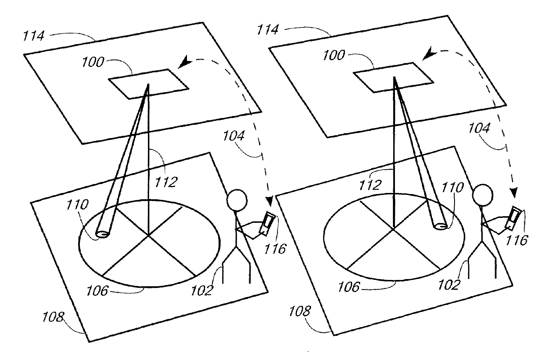
[0020]In one preferred embodiment of the invention, light tracking is accomplished by laying down a two dimensional grid on the ground and assigning each articulable or robotic light a digital multiplex (“DMX”) command that provides the encoders and step motors (that control the articulable or robotic light) the X-Y location of that section of the grid. Any communications protocol, including DMX512-A, RS-485 based communications protocols, or other protocols useful for controlling stage lighting and generally known in the art, may be used to provide a DMX or other command. In an embodiment for an operating room, approximately four inch squares within a fifteen foot circle centered on the center-point of an operating table therein may be provided to form the grid.

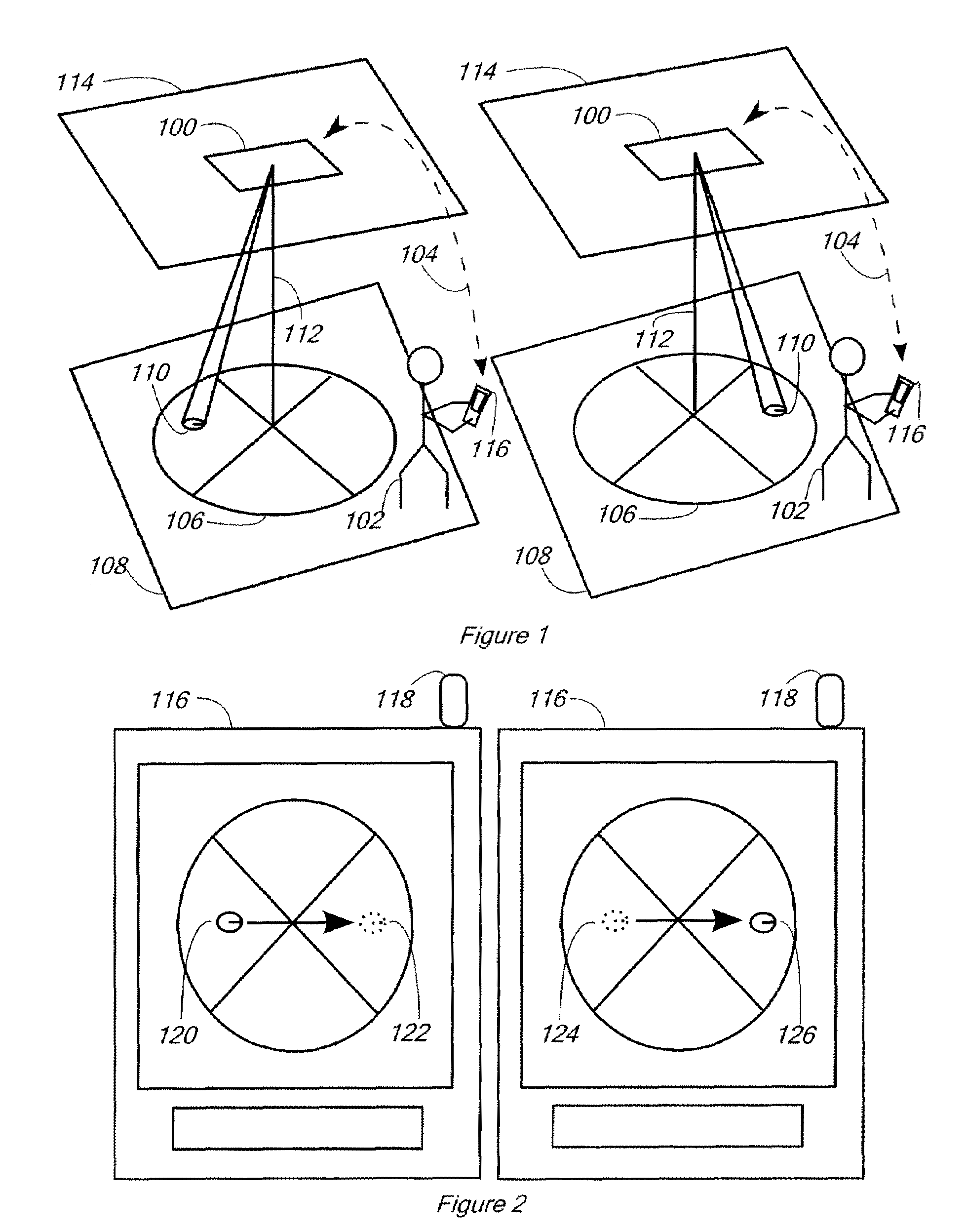
[0021]Once these “addresses” have been assigned in physical space by an installer of the lighting units, a virtual grid is rendered on a GUI interface of a computer, and each corresponding grid mark location in the rendering...


PUM


Abstract

A graphical-user-interface manipulable lighting system is disclosed in which a light source having a position of focus is moved by an articulator adapted to receive and send signals through a control box indicating the current and intended positions of the focus of the light source, and further a computer interface operating wirelessly which graphically displays the current position of the light source and is adapted to allow a user to drag an icon indicating the current position of the light source onto a new intended position thereby resulting in the movement of the light source to the new position.

Description

CROSS-REFERENCE TO RELATED APPLICATIONS[0001]This application claims the benefit of the provisional application No. 60 / 947,747 filed 3 Jul. 2007 and the complete content of this application is incorporated by reference.FIELD OF INVENTION[0002]This invention relates generally to an apparatus and method for controlling the focal point of light sources wirelessly and by utilizing a graphical user interface.BACKGROUND OF THE INVENTION[0003]There is a need for a device which will allow a user to wirelessly and seamlessly manipulate the focal point of a light source in a user-friendly manner. In many applications, light sources must be directed to a target area such as on an actor on a stage. Because these target areas move, the light source must also move with the actor. The light source can be manually moved, as by an operator moving an articulable light source by hand, in order to follow the actor. This can expose the operator to dangerous heights, high temperatures from the light sour...

Claims


Application Information

Patent Timeline
IPC IPC(8): F21V33/00
CPCF21V33/00F21V33/0064H05B37/029F21W2131/406F21W2131/20H05B47/155
Inventor MANGIARDI, JOHN R.GEBBIE, JR., JOHN W.
Owner OPTIMUS LICENSING AG
Why Eureka
Try Eureka