Video processing method

a processing method and video technology, applied in the field of video processing methods, can solve the problems of not having 100% reliability in reality, information may be limited, and the required time is a problem, so as to reduce the load of viewing

Inactive Publication Date: 2009-01-15
KOKUSA ELECTRIC CO LTD
View PDF14 Cites 10 Cited by
  • Summary
  • Abstract
  • Description
  • Claims
  • Application Information

AI Technical Summary

Benefits of technology

[0052]Thus, since images are displayed in decreasing order of amount of displacement from that at the steady state, the load of viewing on a viewer can be reduced even in a case where the presence of occurrence of an event is not clear and all recorded images must be viewed, for example.
[0064]Thus, since the video duration, which is a set of multiple video frames, is a unit of images, a viewer can view them more easily than the case where images in frames are used as the images in the predetermined unit.
[0073]As described above, the video processing method according to the invention can reduce the load of viewing on a viewer even in a case where the presence of occurrence of an event is not clear and all recorded images must be viewed, for example, since images are displayed in decreasing order of amount of displacement from one at a steady state.

Problems solved by technology

However, those kinds of information may be limited under various conditions including bad conditions such as wind, rain and / or snow and backlighting in image recognition processing and may not have 100% reliability in reality.
A required time is a problem here in playing and viewing all recorded images.
Therefore, in order not to miss the image part, a viewer is forced to be highly strained for a long period of time.

Method used


Image

  • Video processing method
  • Video processing method
  • Video processing method

Examples


first embodiment

[0094]First of all, an outline of the playback of this embodiment will be described.

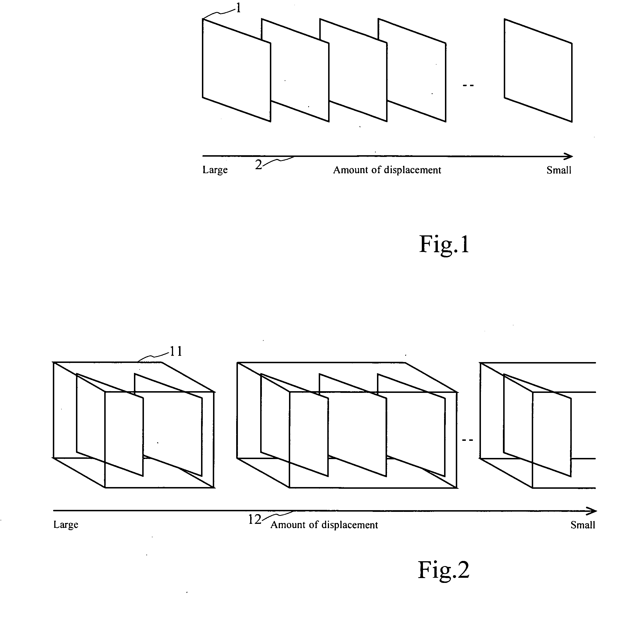
[0095]FIG. 1 shows an example of how images are played.

[0096]More specifically, the horizontal axis is an amount-of-displacement axis 2 with reference to a steady image. The left side shows the maximum amount of displacement, and the right side shows the minimum amount of displacement. A series of images is shown, and one frame (video frame 1) of images is illustrated as a part of the series of images.

[0097]The playback of this embodiment is processing of displaying each one frame sequentially at predetermined time intervals from the left to the right of the amount-of-displacement axis 2 in FIG. 1.

[0098]Here, in this embodiment, the amount of displacement is the opposite indicator of the degree of similarity and can be said as the degree of dissimilarity. In other words, according to this embodiment, images are played in order from the most similar one to the least similar one.

[0099]For easy descript...

second embodiment

[0227]This embodiment describes another detail example of the initial operation in the above-described video processing apparatus.

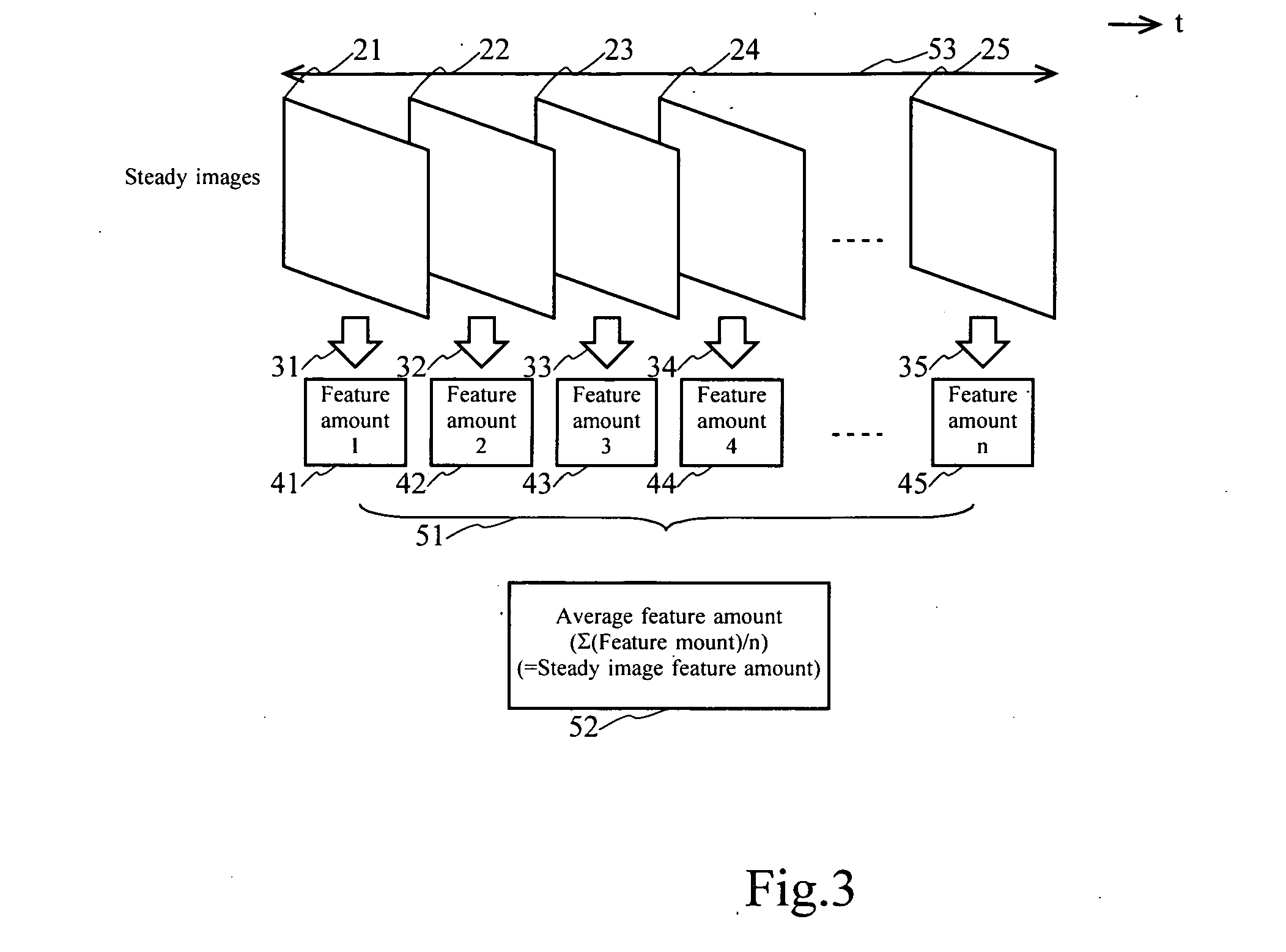
[0228]In step 201, one or multiple sets of a steady image and multiple assumed abnormal images from which an abnormality (which is a difference from the steady image) should be detected near the steady image is or are prepared.

[0229]In step 202, a difference in feature amount vector between the steady image and the assumed abnormal images is obtained in each of the sets. The feature amount vector here is a statistical value calculated evenly from the entire area of an image and contains, as components, all of the RGB histograms and intensity gradient distributions in the areas resulting from the division of an image by a predetermined size. The number of components may be as high as about 1000.

[0230]In step 203, the components of the feature amount vector with low correlations in each set are selected in decreasing order. The correlation can be estimated ...


PUM


Abstract

A video processing apparatus obtains information describing the amount of displacement of images in multiple predetermined units (such as video durations) imaged by an imaging apparatus from an image at steady state, which is a reference, and displays the images in the multiple predetermined units in decreasing order of amounts of displacement based on the obtained information describing the amounts of displacement.

Description

BACKGROUND OF THE INVENTION[0001]1. Field of the Invention[0002]The present invention relates to a video processing method and, in particular, it relates to a video processing method that can reduce the load of viewing on a viewer even in a case where all recorded images must be viewed since the presence of the occurrence of an event is not clear.[0003]2. Description of the Related Art[0004]Conventionally, a video surveillance system is deployed in public facilities such as a hotel, a building, a convenience store, a financial institution, a dam and a road for the purpose of the suppression of crimes and / or the prevention of accidents. Such a video surveillance system photographs a subject under surveillance with an imaging apparatus such as a camera and transmits the images to a surveillance center such as a management office and a security room. A surveillance person may monitor the images and be alert on and / or record or save the image or images for the purpose or as required.[00...

Claims


Application Information

Patent Timeline
Patent Type & Authority Applications(United States)
IPC IPC(8): H04N9/74
CPCG06T7/2033G11B27/105H04N5/144H04N5/76H04N5/765H04N5/77H04N9/8205H04N5/781H04N5/783H04N5/85H04N5/907H04N7/185H04N5/775G06T7/246
Inventor HIRAI, SEIICHIHASHIGUCHI, NAOKITAKADA, TOMOMI
Owner KOKUSA ELECTRIC CO LTD
Why Eureka
Try Eureka