
Resin cage for ball bearing
- Summary
- Abstract
- Description
- Claims
- Application Information
AI Technical Summary
Benefits of technology
Problems solved by technology
Method used
Image

Examples
Embodiment Construction
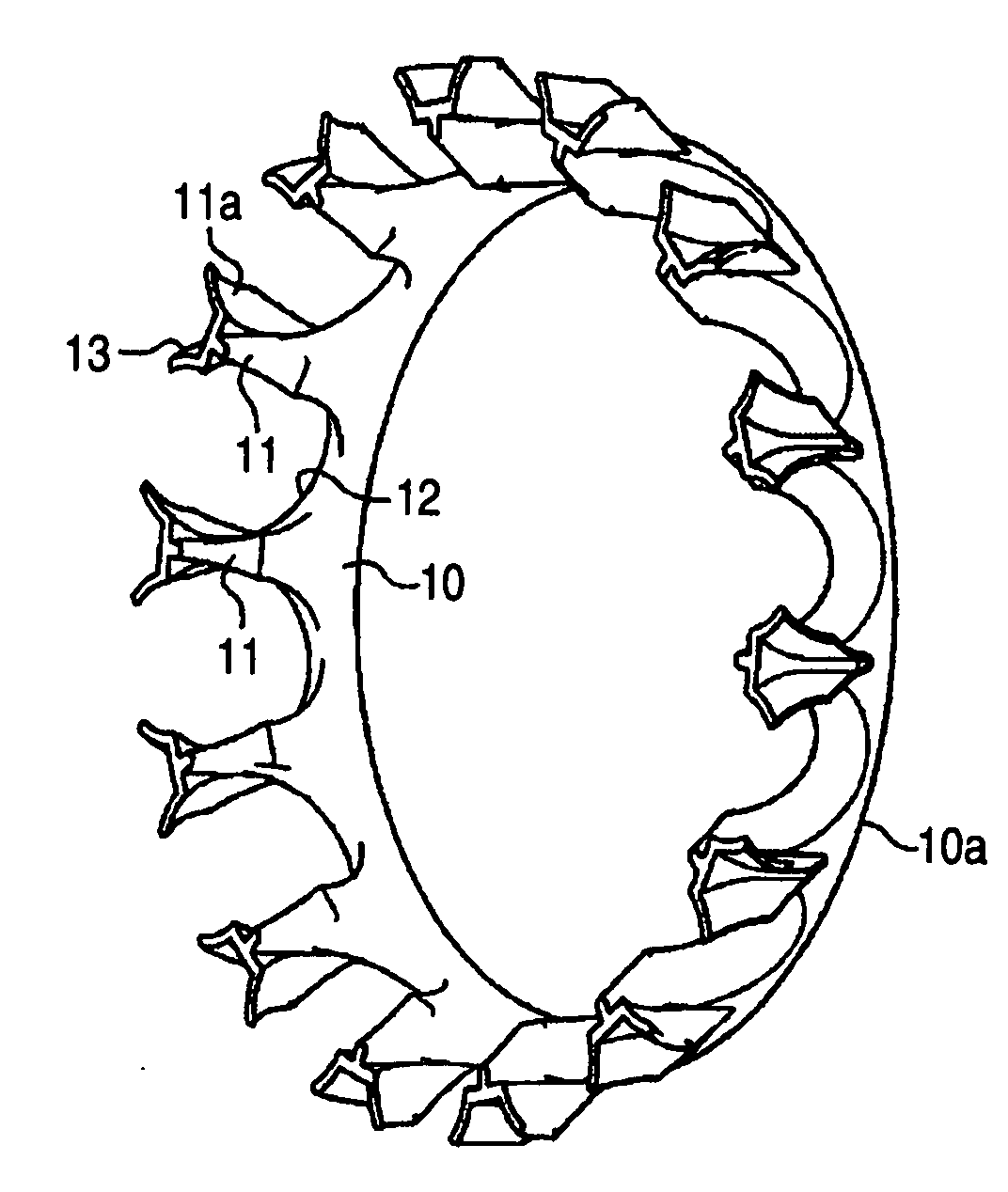
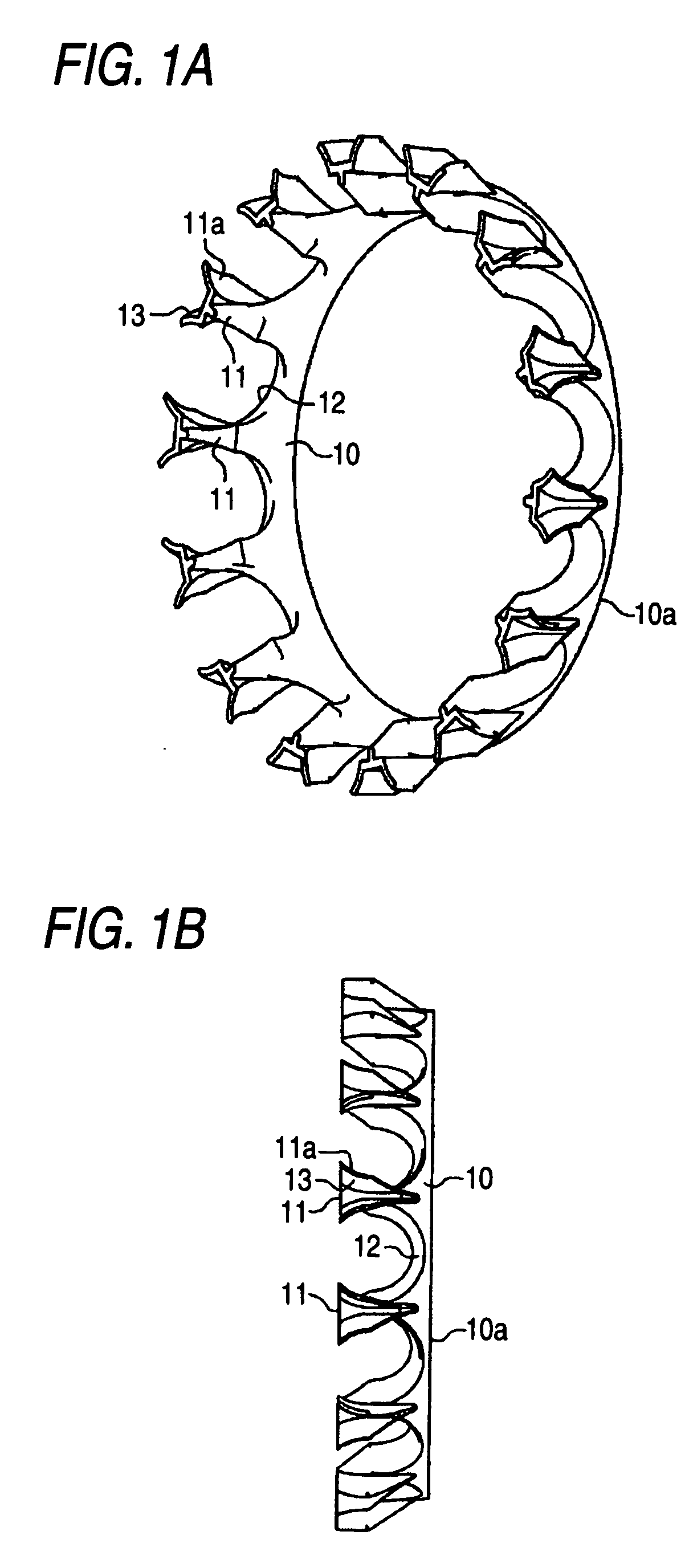
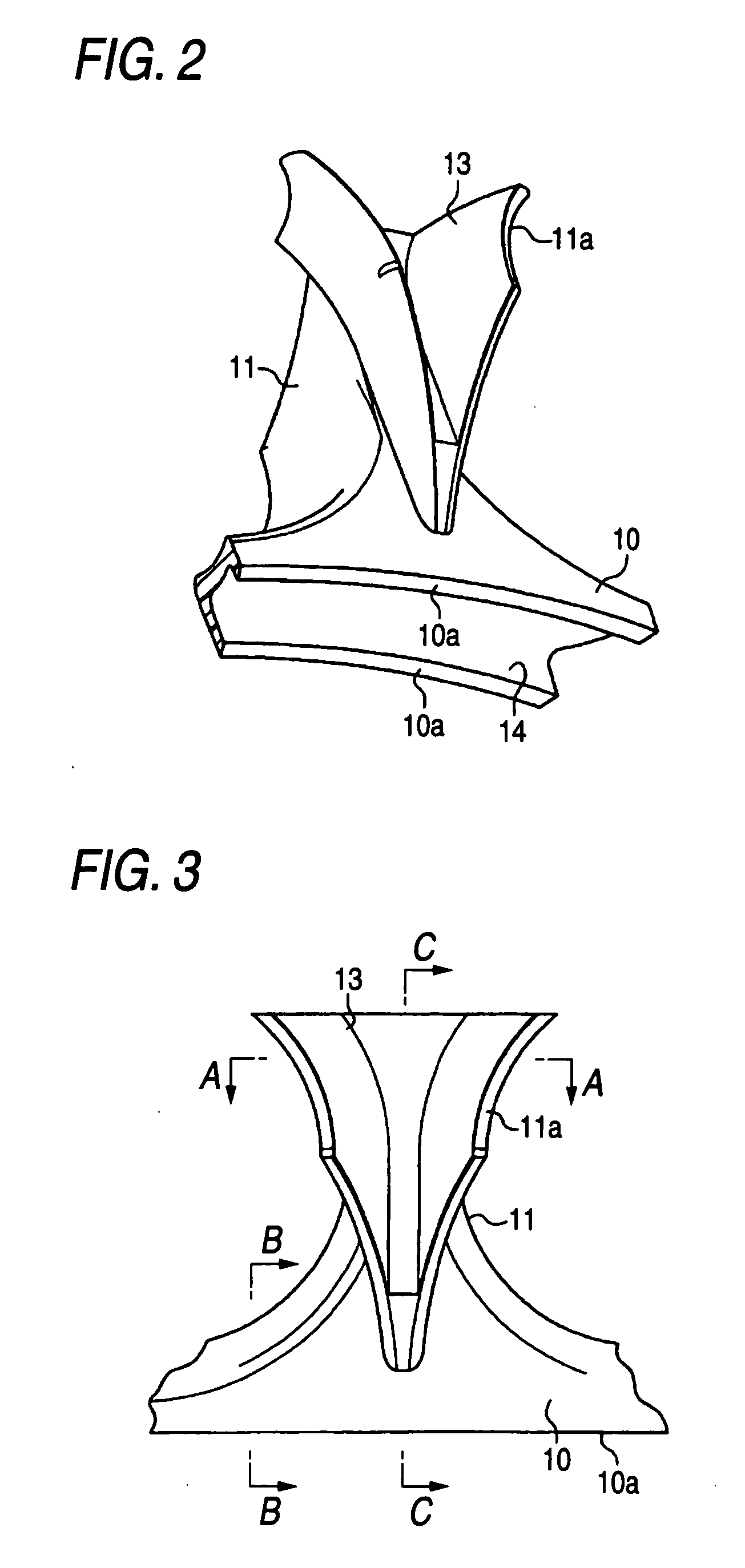
[0028]Hereinafter, a resin cage for a ball bearing according to an embodiment of the invention will be-described in detail with reference to FIGS. 1A to 4C. The cage according to the present embodiment is formed by resin injection molding, and is employed in an angular contact ball bearing.
[0029]FIG. 1A is a perspective view illustrating the perspective structure of such a resin cage for the ball bearing according to an embodiment of the invention. FIG. 1B is a side view illustrating the side structure of the resin cage for the ball bearing according to the embodiment of the invention. As illustrated in FIGS. 1A and 1B, the resin cage is formed into a substantially crown-like shape, and includes an annular base portion 10, and a plurality of claw portions 11 (the number of the claw portions 11 is, e.g., 14 in an example illustrated in FIGS. 1A and 1B) which are formed to be arranged at constant intervals on the circumference of the base portion 10 and to protrude therefrom. A concav...
PUM
 Abstract
Description
Claims
Application Information