Liquid container

Inactive Publication Date: 2006-09-14
SEIKO EPSON CORP
View PDF15 Cites 24 Cited by
  • Summary
  • Abstract
  • Description
  • Claims
  • Application Information

AI Technical Summary

Benefits of technology

[0030] According to the liquid container having such a structure, the passage has a rectangular section. As compared with the case in which the formation is carried out by a passage having a circular section, therefore, a wasteful space is not left between the passages which are provided in parallel so that a complicated passage can be formed at a high density. Also in the case in which the air bubble trap passage is formed by resin molding, moreover, a moldability can be enhanced. In addition, in the case in which the passage has a rectangular section, a stagnation area having a slow flow is formed in the corner portions of the rectangular passage section and the corner portions in an upper part function as the air bubble collecting spaces for accumulating the air bubbles separated by the flow direction converting portion differently from the case of the passage having a circular section. Therefore, the function

Problems solved by technology

When the air bubbles floating in the ink liquid are stuck to a surface of the sensor, the air bubbles thus stuck causes a change in a residual oscillation so that the presence of the ink cannot be detected accurately.
Consequently, there is a possibility that it might be erroneously detected that the liquid level of the ink is reduced.
Even if the sensor is provided in the vicinity of the liquid supply portion, however, the air bubbles mixed into the ink are stuck to the sensor and it is thus detected erroneously that the residual amount of the liquid in the liquid containing portion is zero in some cases.
In the techni

Method used


Image

  • Liquid container
  • Liquid container
  • Liquid container

Examples


Embodiment Construction

[0041] An example of an embodiment of a liquid container according to the invention will be described below in detail with reference to the drawings.

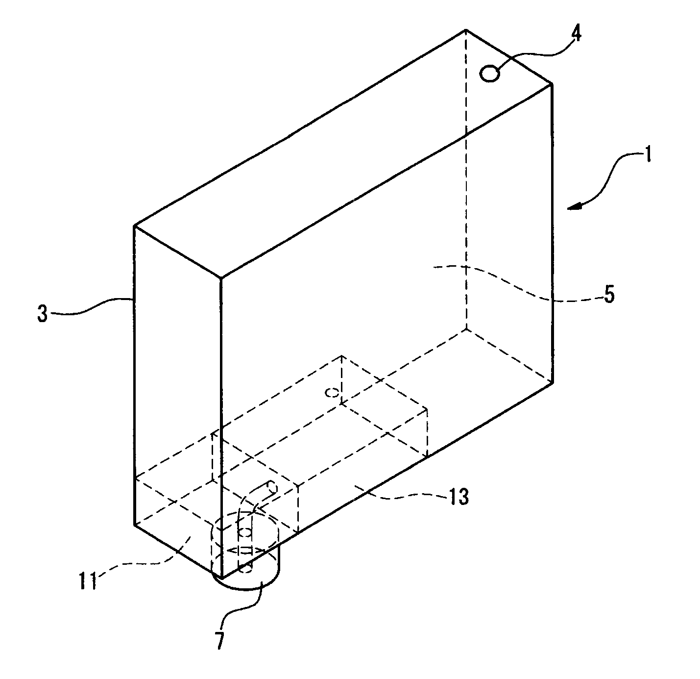
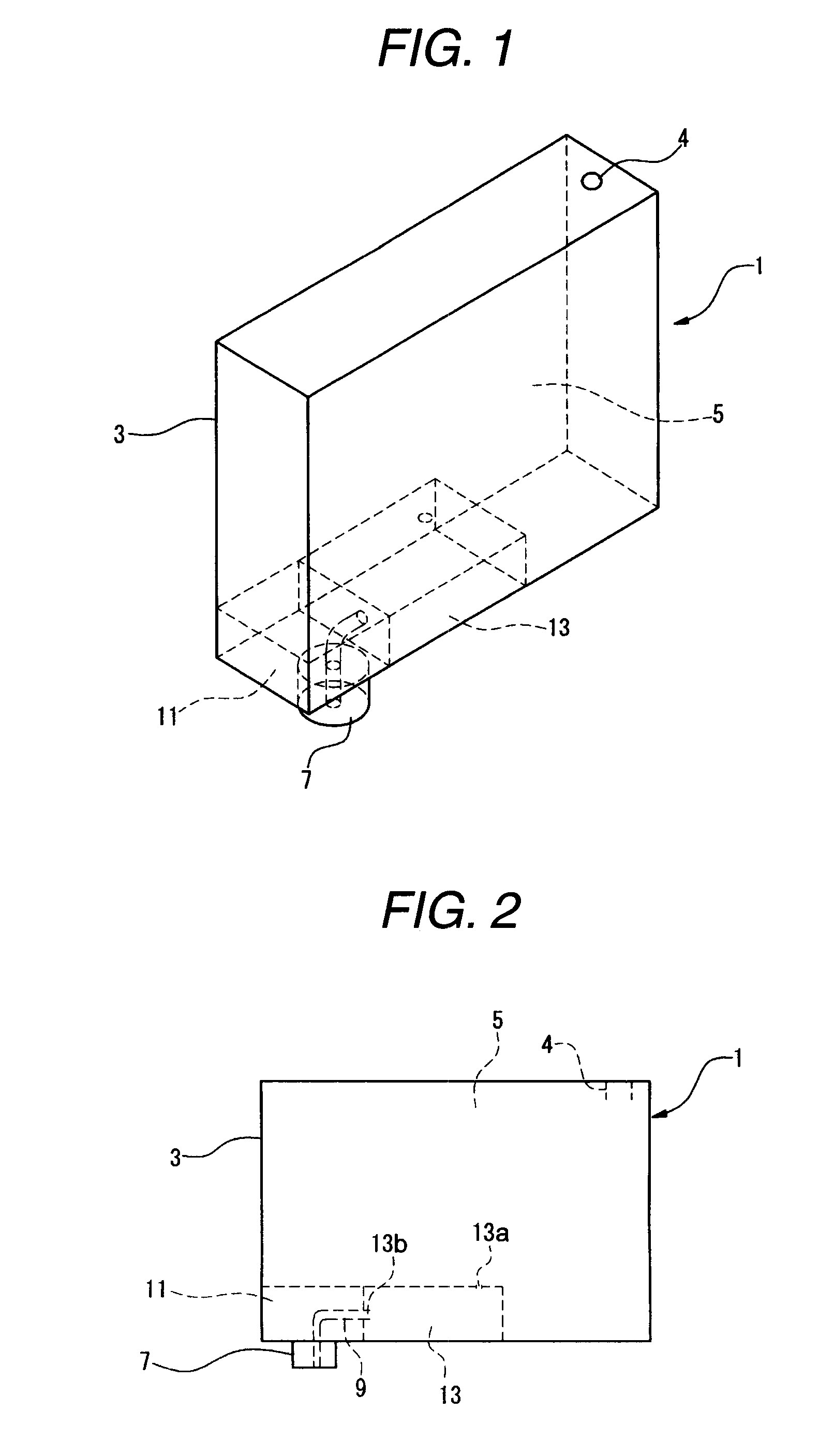
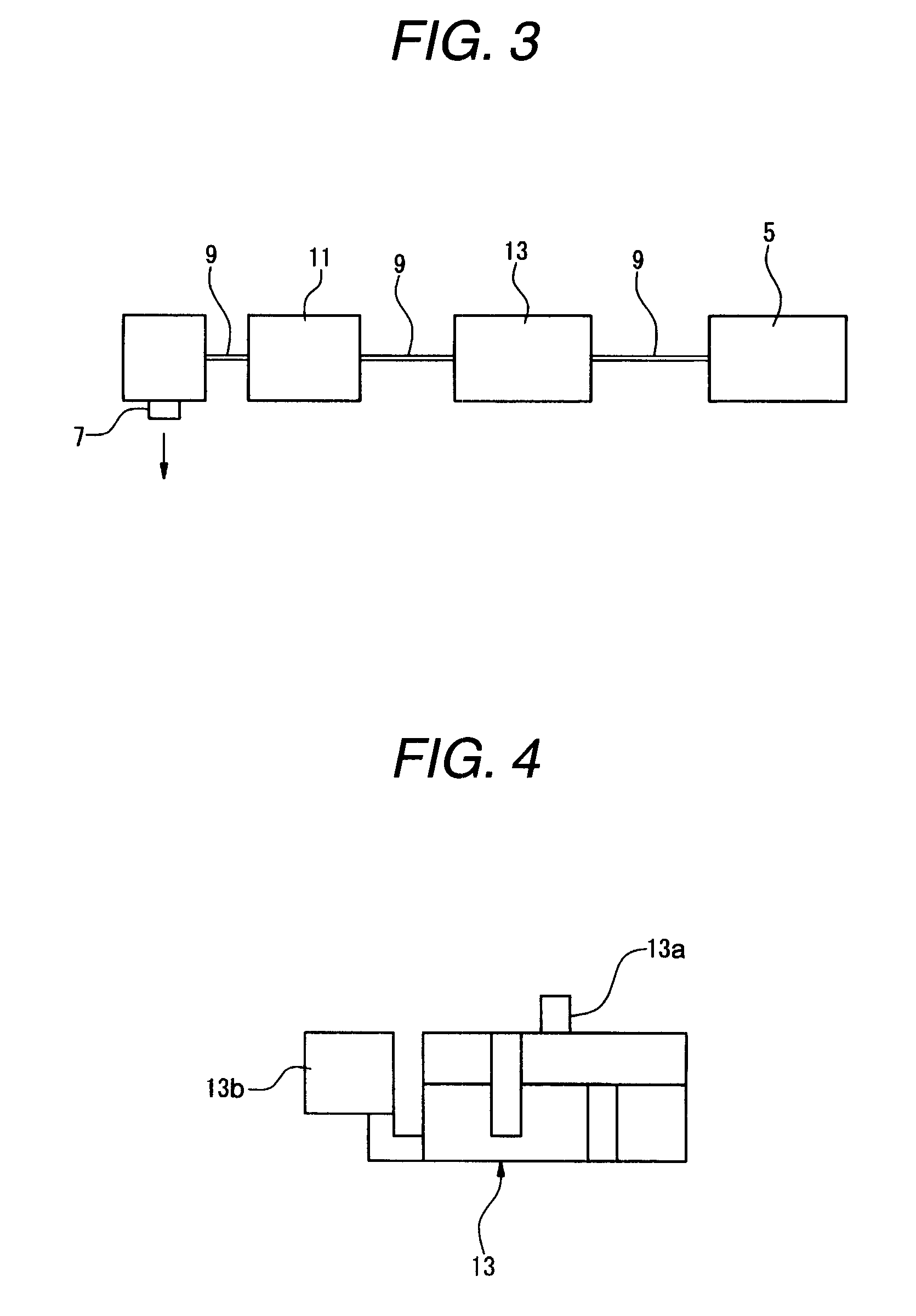
[0042] FIGS. 1 to 8 show an embodiment of a liquid container according to the invention, and FIG. 1 is a schematic perspective view showing the liquid container according to the embodiment of the invention, FIG. 2 is a side view showing the liquid container illustrated in FIG. 1, FIG. 3 is a typical view showing a path through which a liquid flows in the liquid container illustrated in FIG. 1, FIG. 4 is a side view showing an air bubble trap passage illustrated in FIG. 1, FIG. 5 is a plan view showing the air bubble trap passage illustrated in FIG. 4, FIG. 6 is a sectional view taken along a VI-VI line in FIG. 5, FIG. 7 is a view seen in an arrow of VII in FIG. 5, and FIG. 8 is a view seen in an arrow of VIII in FIG. 7.

[0043] In a printer of an ink jet type, the liquid container according to the embodiment is an ink cartridge 1 to be ...


PUM


Abstract

A liquid container includes, in a container body 3, an ink containing portion 5, an ink supply.portion 7, an ink leading path 9 for leading an ink stored in the ink containing portion 5 to the ink supply portion 7, and an atmosphere communication port 4, and an ink end sensor 11 for detecting an inflow of a gas to the ink leading path 9, thereby detecting that a residual amount of the ink in the ink containing portion 5 is zero is provided in the middle of the ink leading path 9, and furthermore, an air bubble trap passage 13 for catching air bubbles mixed in the ink is provided in the ink leading path 9 between a detecting position of the ink end sensor 11 and the ink containing portion 5.

Description

BACKGROUND OF THE INVENTION [0001] 1. Technical Field of the Invention [0002] The present invention relates to a liquid container of an atmosphere communication type which is suitable as an ink cartridge to be attached to an ink jet printer, for example. [0003] 2. Description of the Related Art [0004] As an ink cartridge (a liquid container) to be attached to an ink jet printer, there have variously been proposed an atmosphere communication type comprising, in a container body to be attached to the printer, an ink containing portion (a liquid containing portion) for accommodating an ink, an ink supply portion (a liquid supply portion) to be connected to a print head (a liquid ejection portion) on the printer side, an ink leading path (a liquid leading path) for leading the ink stored in the ink containing portion to the ink supply portion, and an atmosphere communication port for introducing atmosphere from an outside into the ink containing portion with a consumption of the ink in ...

Claims


Application Information

Patent Timeline
IPC IPC(8): B41J2/175
CPCB41J2/17513B41J2/19B41J2002/17583B41J2/17566B41J2/175
Inventor KATSUMURA, TAKAYOSHI
Owner SEIKO EPSON CORP
Why Eureka
Try Eureka