Automated Oil-Change System and Method

Inactive Publication Date: 2006-05-11
EVANS LARRY DOUGLAS
View PDF33 Cites 11 Cited by
  • Summary
  • Abstract
  • Description
  • Claims
  • Application Information

AI Technical Summary

Benefits of technology

[0013] Before reaching the predetermined time, the three-way oil pump valve, in certain other embodiments, may be set to allow the flow of oil from the first oil container to the oil pump and prevent the flow of oil from the second oil container to the oil pump. The three-way return valve may be set to allow the flow of oil from the oil pan to the first oil container and prevent the flow of oil from the oil pan to the second oil container. The three-way vacuum valve may be set to allow the flow of gas from the first oil container to the vacuum system of the engine and prevent the flow of gas from the second oil container to the vacuum system of the engine. The method may further comprise the steps of: (1) resetting the three-oil pump valve once the predetermined time is reached to allow the flow of oil from the second oil container to the oil pump and prevent the flow of oil from the first oil container to the oil pump; (2) resetting the three-way return valve once the predetermined time is reached to allow the flow of oil from the oil pan to the second oil container and prevent the flow of oil from the oil pan to the first oil container; and (3) resetting the three-way vacuum valve once the predetermined time is reached to allow the flow of gas from the second oil container to the vacuum system of the engine and prevent the flow of gas from the first oil container to the vacuum system of the engine.
[0014] In certain other embodiments, the method may further comprise the step of the resetting of the settings of the three-way oil pump valve, the three-way return valve, and the three-way vacuum valve, once the predetermined time is reached, in a staggered manner so to minimize the mixture of oil from first oil container and oil from the secon

Problems solved by technology

Neither of these alternatives is either cost or time efficient, and generally lead to the oil being changed too infrequently.
Do-it-yourself alternatives generally have failed.
However, the adoption of these devices as well as the purchase of other specialized tools that aid in the oil changing process has been poor due to the complexity of the devices and tools and expense.
Further, changing the oil “the old fashion way” generally requires the car owner to reach areas of the car that are hard to get to and come in contact with oily car parts.
This makes the task difficult, dirty and time consuming to the car owner.
As a result, many people who rely on such methods tend to put off the job, which, in many instances, causes the oil to be changed too infrequently.
This leads to increased wear and tear to the engines of many vehicles.
However, this

Method used


Image

  • Automated Oil-Change System and Method
  • Automated Oil-Change System and Method

Examples


Example

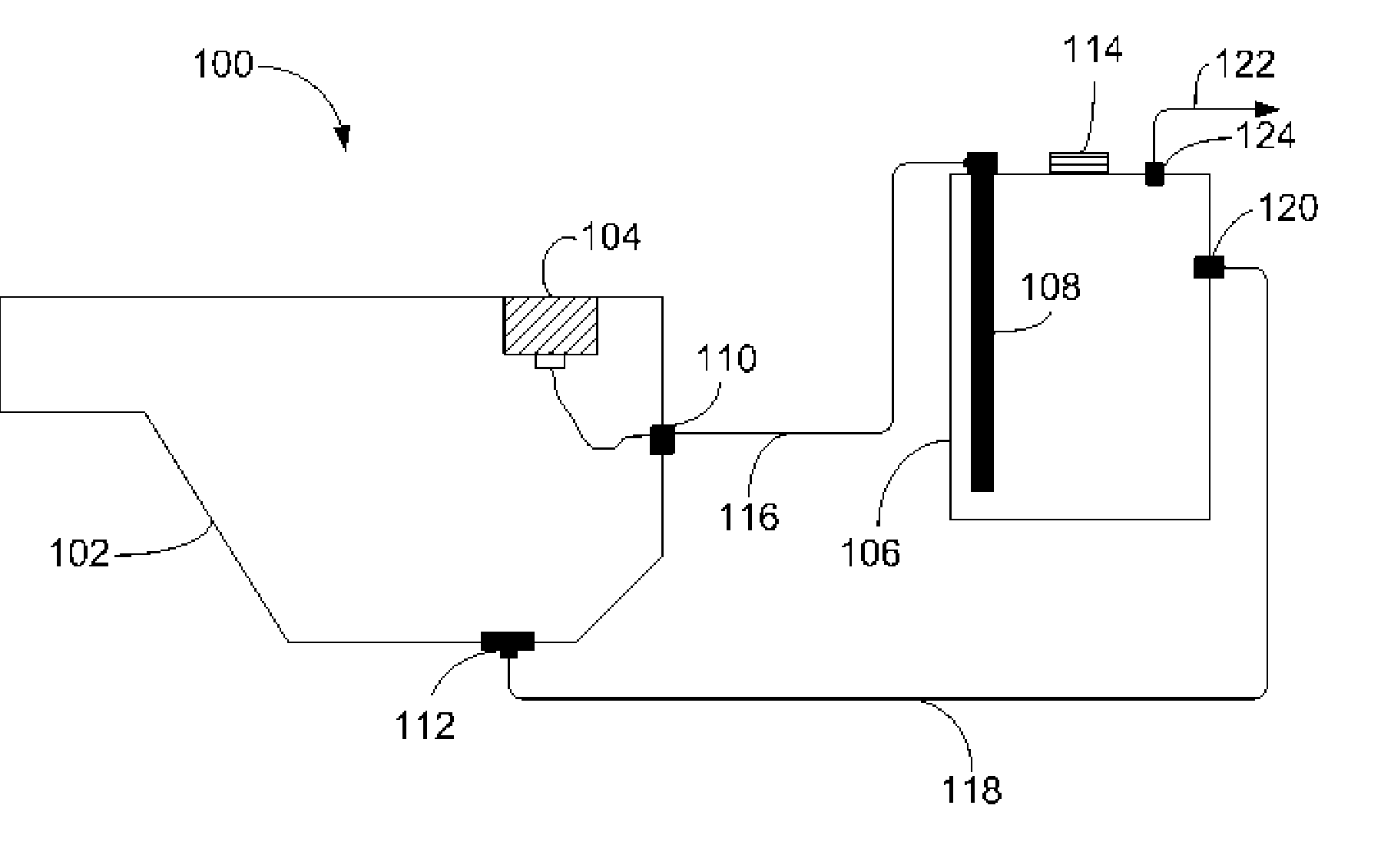
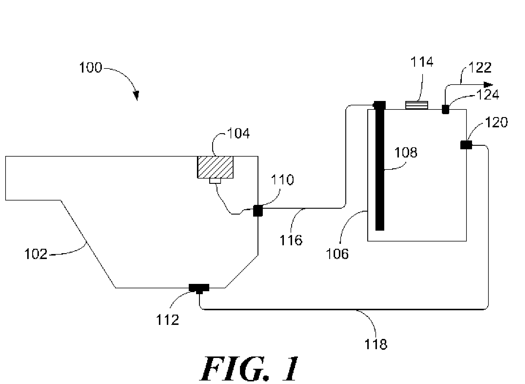
[0017] Referring now to the figure, where the various numbers represent like parts throughout the several views, FIG. 1 shows an exemplary embodiment of the present invention, an Automated Oil-Change System. The System, generally referred to by reference number 100, may include an oil pan 102, an oil pump 104, an oil container 106, and an oil strainer 108. It will be clear to those skilled in the art that the present invention could be used for replacing any type of engine fluid and be used in any type of engine.

[0018] Various connections may be made between the major components of System 100. The oil pan 102 may include an oil pan commonly known in the art that is modified as described below. The oil pan 102 may be located in the preferred location for the engine type. The oil pump 104 may be connected to the inner side of the top wall of the oil pan 102 by methods commonly known in the art. The oil pump 104 may include any of those commonly known in the art, including those commo...


PUM


Abstract

The present invention may provide an automatic oil-change system for an engine comprising: a first oil container, a second oil container and means for switching between the first oil container and the second oil container. The switching means may provide the engine with oil from the first oil container until a predetermined time and once a predetermined time is reached, the switching means may provide the engine with oil from the second oil container.

Description

TECHNICAL FIELD [0001] The present invention relates to changing the motor oil in an engine. In particular, the present invention relates to automated systems and methods for changing the motor oil in an engine. BACKGROUND OF THE INVENTION [0002] Every 3000-5000 miles car owners should have the oil changed in their automobiles to prevent excessive engine wear. The current choices that car owners have for completing this necessary preventative maintenance generally includes do-it-yourself alternatives or having the automobile serviced at a service center. Neither of these alternatives is either cost or time efficient, and generally lead to the oil being changed too infrequently. [0003] Do-it-yourself alternatives generally have failed. Several patents, such as U.S. Pat. No. 5,372,219 to Peralta and U.S. Pat. No. 4,884,660 to Bedi, attempt to provide a method to speed up the oil change process. However, the adoption of these devices as well as the purchase of other specialized tools t...

Claims


Application Information

Patent Timeline
IPC IPC(8): F01M1/04
CPCF01M11/04
Inventor EVANS, LARRY DOUGLAS
Owner EVANS LARRY DOUGLAS
Why Eureka
Try Eureka