Standby powering for power over ethernet

Active Publication Date: 2017-01-12
MICROSEMI
View PDF1 Cites 13 Cited by
  • Summary
  • Abstract
  • Description
  • Claims
  • Application Information

AI Technical Summary

Benefits of technology

[0014]Accordingly, it is a principal object of the present invention to overcome at least some of the disadvantages of prior art powering arrangements. This is accomplished in the present embodiments by providing a respective electronically controlled switch in series with the output of each PD so as to prevent the flow of current from the PD via an ORing circuit when opened, and allow the flow of current from the PD via the ORing circuit when closed. A control circuit having a timer functionality is further provided, w

Problems solved by technology

There is one difficulty in PoE powering arrang

Method used


Image

  • Standby powering for power over ethernet
  • Standby powering for power over ethernet
  • Standby powering for power over ethernet

Examples


Example

[0022]Before explaining at least one embodiment of the invention in detail, it is to be understood that the invention is not limited in its application to the details of construction and the arrangement of the components set forth in the following description or illustrated in the drawings. The invention is applicable to other embodiments or of being practiced or carried out in various ways. Also, it is to be understood that the phraseology and terminology employed herein is for the purpose of description and should not be regarded as limiting.

[0023]The invention is being described as an Ethernet based network, with a powered device being connected thereto. It is to be understood that the powered device is preferably an IEEE 802.3 compliant device preferably employing a 10Base-T, 100Base-T or 1000Base-T connection.

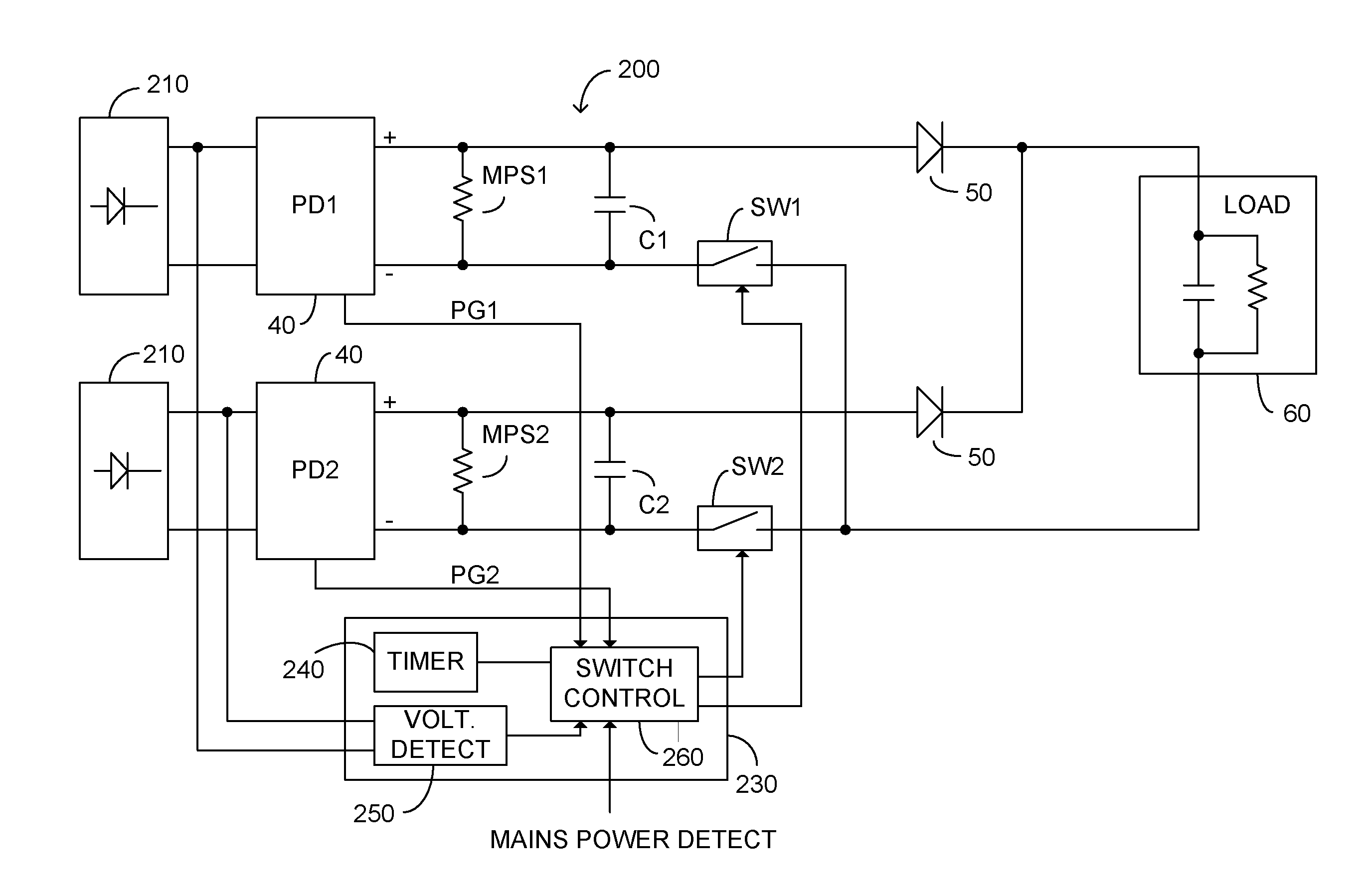
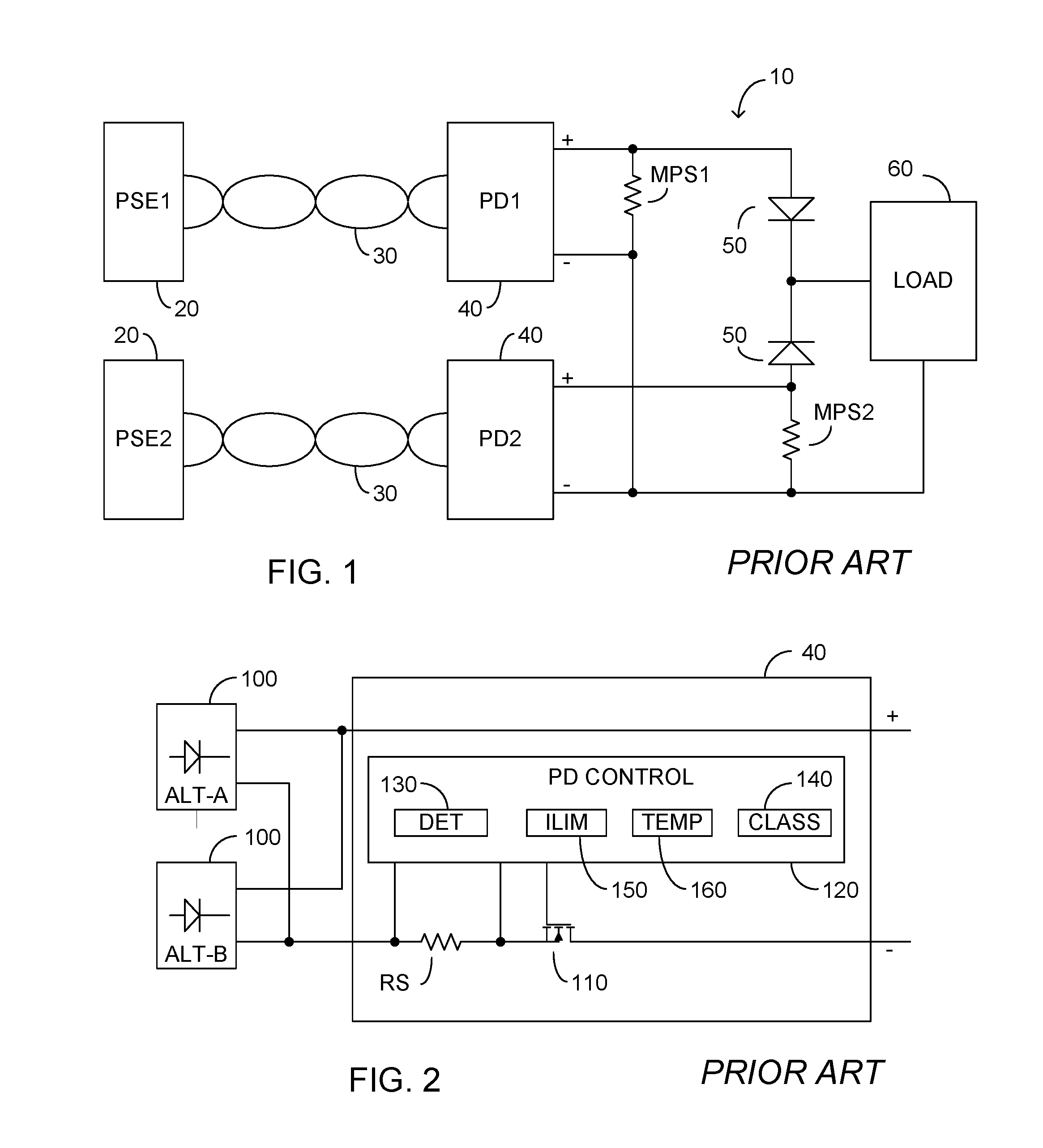
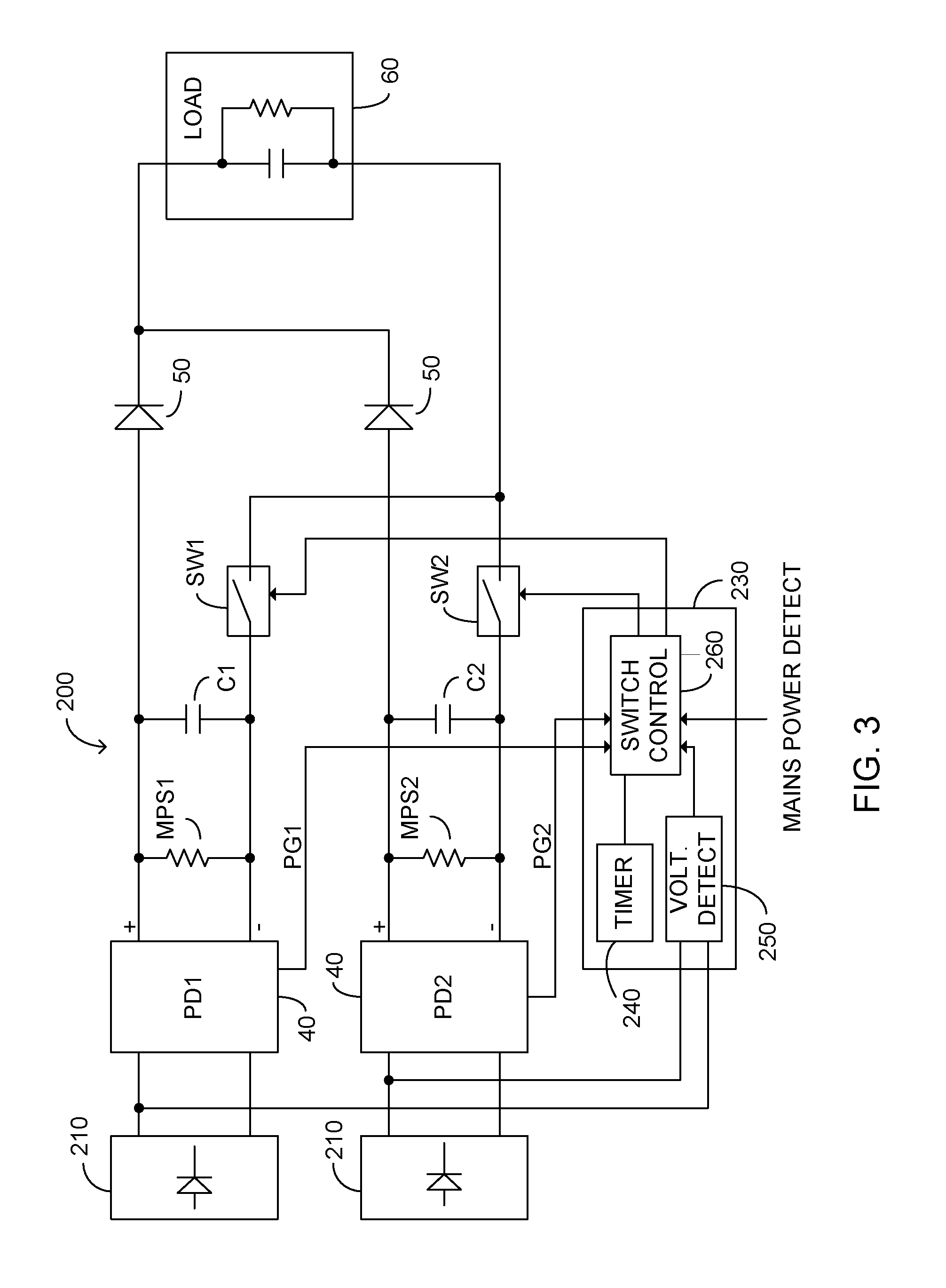
[0024]FIG. 3 illustrates a PoE powering arrangement 200 according to certain embodiments. As described above in relation to FIG. 2 input circuitry typically comprises a pa...


PUM


Abstract

A respective electronically controlled switch is provided in series with the output of each PD. A control circuit having a timer functionality is further provided, with the electronically controlled switches responsive to the control circuit. Upon detection that a second PD, defined temporally, is provided with operating power, the respective electronically controlled switch is maintained open for a predetermined hold-off time period sufficient to ensure detection by the respective PD control state machine of the completion of startup. After expiration of the predetermined hold-off time period, the respective electronically controlled switch is closed thus enabling normal operation.

Description

BACKGROUND OF THE INVENTION[0001]The invention relates generally to the field of power over local area networks, particularly Ethernet based networks, and more particularly to a method and apparatus arranged to allow for multiple independent powered device to support a single load.[0002]Power over Ethernet (PoE), in accordance with both IEEE 802.3af-2003 and IEEE 802.3at-2009, each published by the Institute of Electrical and Electronics Engineers, Inc., New York, the entire contents of each of which is incorporated herein by reference, defines delivery of power over a set of 2 twisted wire pairs without disturbing data communication. The aforementioned standards particularly provide for a power sourcing equipment (PSE) and a powered device (PD). The power sourcing equipment is configured to detect the PD by ascertaining a valid signature resistance, and to supply power over the 2 twisted wire pairs only after a valid signature resistance is actually detected.[0003]The HD BaseT Alli...

Claims


Application Information

Patent Timeline
IPC IPC(8): H04L12/10
CPCH04L12/10
Inventor RIMBOIM, POLDIROZENBLAT, LAZARMATTOCKS, DENNIS L
Owner MICROSEMI
Why Eureka
Try Eureka