Injection nozzle and method for injection molding

Inactive Publication Date: 2004-03-30
HUSKY INJECTION MOLDING SYST LTD
View PDF12 Cites 10 Cited by
  • Summary
  • Abstract
  • Description
  • Claims
  • Application Information

AI Technical Summary

Benefits of technology

The present invention provides an injection nozzle for injection molding plastic resin from a source of molten resin to a mold cavity, which comprises: a mold cavity; an injection nozzle with a nozzle body and a nozzle tip and having an internal flow channel therein communicating with an injection orifice which in turn communicates with said mold cavity for transportation of molten resin to the mold cavity; a valve gate nub area between the mold cavity and injection orifice; a valve stem mounted in the injection nozzle; and means to move the valve stem between an open position retracted from the injection orifice permitting the flow of resin to the mold cavity, a closed position blocking the injection orifice and preventing flow of resin to the mold cavity, and an advanced position within the valve gate nub area to assist in ejection of a molded part and to clear the valve gate nub area. In the preferred embodiment the valve gate nub area includes a passageway between the mold cavity and injection orifice with an annul

Problems solved by technology

This considerably complicates mold construction and does not appear to provide a foolproof nub removal and ejection system.
A sy

Method used


Image

  • Injection nozzle and method for injection molding
  • Injection nozzle and method for injection molding
  • Injection nozzle and method for injection molding

Examples


Example

)

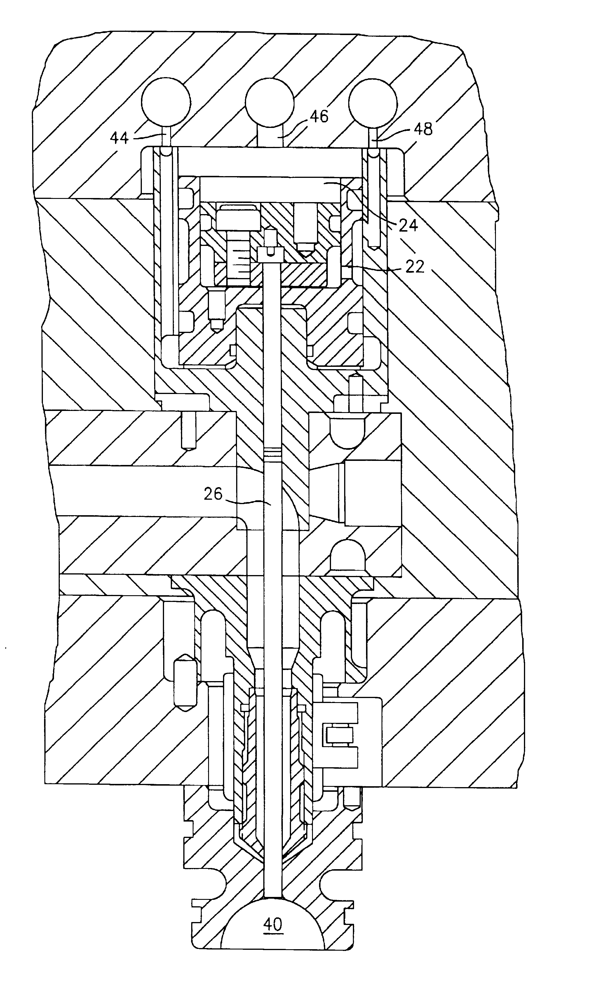
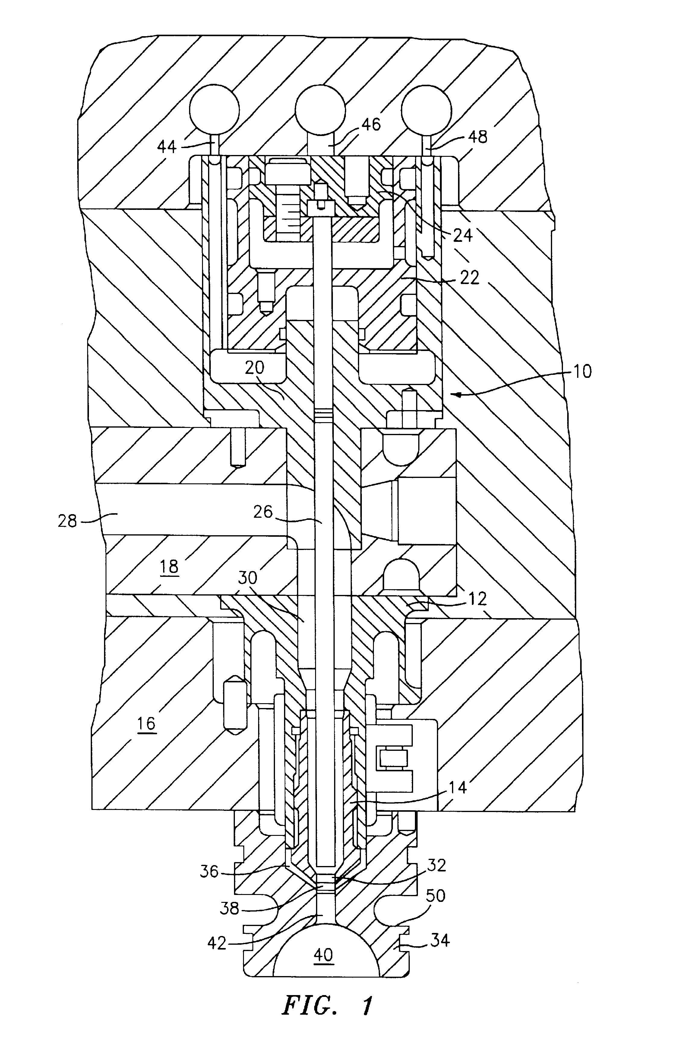
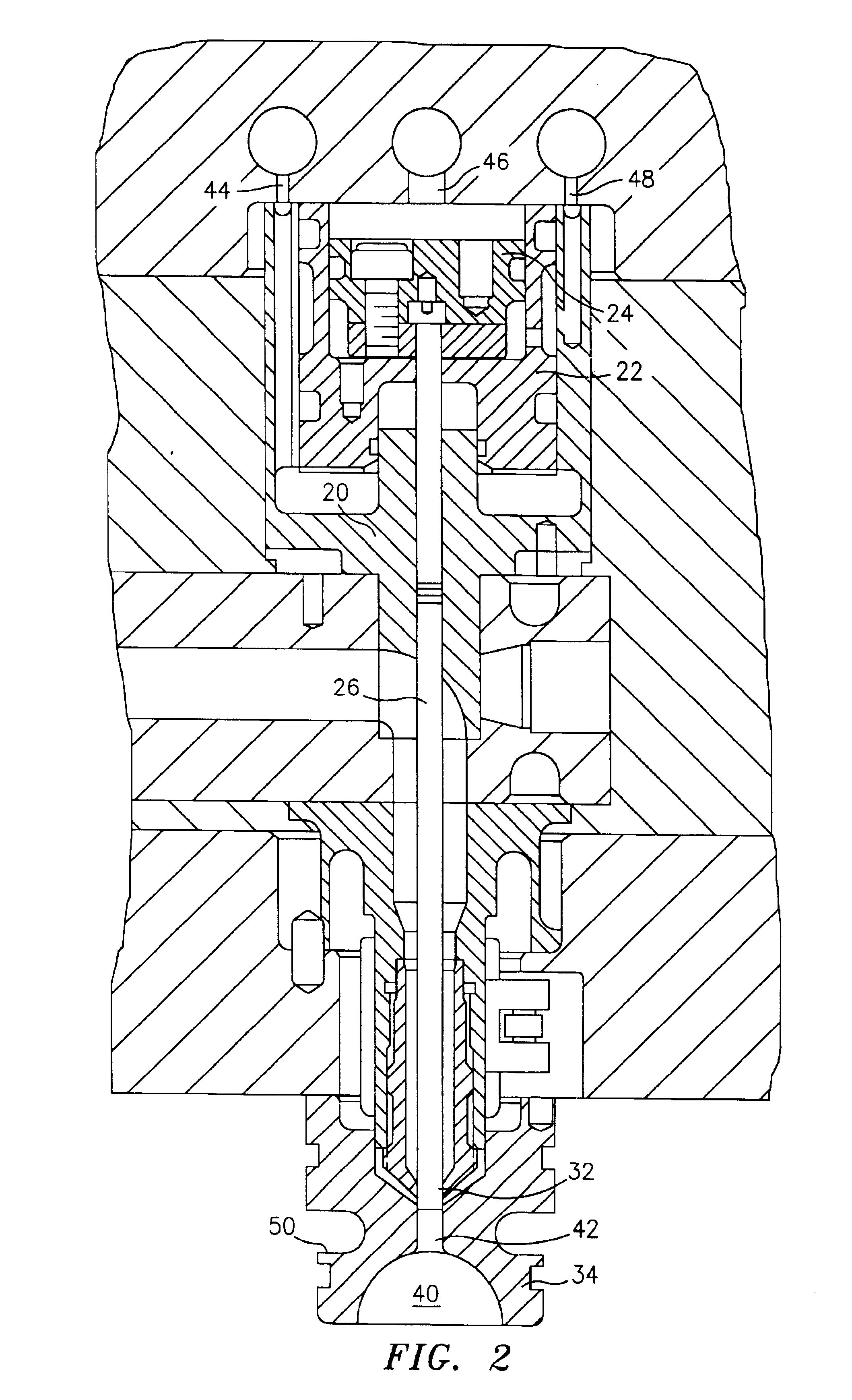
Referring to the drawings which show a preferred embodiment of the nozzle assembly of the present invention, FIGS. 1-3 show the nozzle assembly in each of three valve stem positions. FIG. 1 shows injection nozzle 10 including nozzle housing 12 and nozzle tip 14 secured thereto. The injection nozzle is located in mold manifold plate 16 and supporting manifold 18. Mounted in manifold 18 is valve bushing 20 that contains two pneumatic pistons 22, 24 to which is attached valve stem 26.

Melt channel 28 in manifold 18 is connected to central melt channel 30 in nozzle housing 12 which in turn leads to injection orifice or gate orifice 32 in gate pad 34. Insulator 36 occupies the space between nozzle tip 14 and gate pad 34 and also contains a melt channel opening 38 therein. When the valve stem 26 is in the fully retracted position as shown in FIG. 1 resin can be injected through the melt channels to fill mold cavity 40 in a known fashion. This mold cavity has a gate nub 42 so that when the...


PUM

PropertyMeasurementUnit
Flow rateaaaaaaaaaa
Areaaaaaaaaaaa
Distanceaaaaaaaaaa

Abstract

A valve stem is mounted in a nozzle body, with the valve stem moving from an open position retracted from the injection orifice permitting the flow of resin to the mold cavity, to a closed position blocking the injection orifice and preventing the flow of resin to the mold cavity, and to an advanced position within the gate nub area to assist in the ejection of a molded part and clear the gate nub area.

Description

BACKGROUND OF THE INVENTIONWhen injection molding plastic preforms, as for example preforms of polyethylene terephthalate (PET), some systems form a gate nub or projection area from the molded part that is allowed to solidify on the molded part and is later removed from the molded part in a subsequent operation. This gate nub or projection is a depository for undesirable resin crystallinity that typically forms in the mold gate area. If the nub is subsequently cut off one has a molded preform which is free of gate crystallinity. Such a system is shown in U.S. Pat. No. 4,588,370 to Ichizawa et al., patented May 13, 1986.A second approach is to cause the gate nub to break off the molded part during mold opening and then eject the removed nub from the gate area when the mold is open. This is shown in Japanese Patent Application No. 52-151358, published Dec. 15, 1977. In this procedure the valve stem of a hot runner has a "gate puller" undercut machined into its end so that the gate nub...

Claims


Application Information

Patent Timeline
IPC IPC(8): B29C45/28B29C45/27
CPCB29C45/281B29C45/40B29C2045/2872
Inventor CATOEN, BRUCEPURI, RAJAN
Owner HUSKY INJECTION MOLDING SYST LTD
Why Eureka
Try Eureka