Image Signal Converting Apparatus And Image Display Apparatus

a technology of image signal and converting apparatus, which is applied in the direction of electrical apparatus, color television details, instruments, etc., can solve the problems of achieve the effect of improving image luminance and deterioration of image color reproducibility

Active Publication Date: 2009-04-16
SANYO ELECTRIC CO LTD
View PDF3 Cites 3 Cited by
  • Summary
  • Abstract
  • Description
  • Claims
  • Application Information

AI Technical Summary

Benefits of technology

[0011]Therefore, while intending to improve the luminance of an image by using the fourth color component light, deterioration of color reproducibility of the image caused by the use of fourth color component light can be controlled.

Problems solved by technology

Thus, color reproducibility of the image is deteriorated by using the yellow component light.

Method used


Image

  • Image Signal Converting Apparatus And Image Display Apparatus
  • Image Signal Converting Apparatus And Image Display Apparatus
  • Image Signal Converting Apparatus And Image Display Apparatus

Examples


first embodiment

(Schematic Description of Projection Image Display Apparatus)

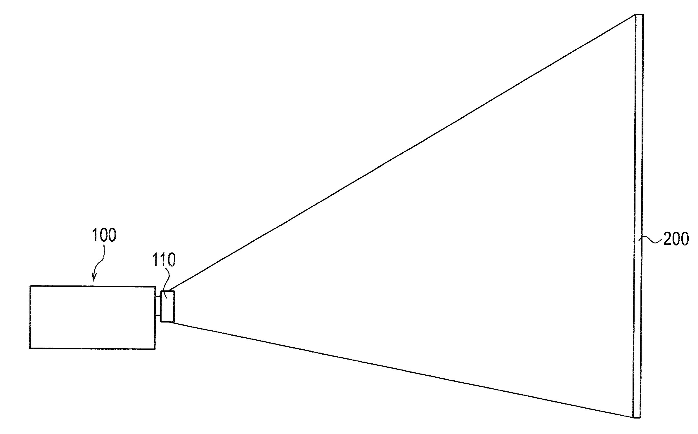
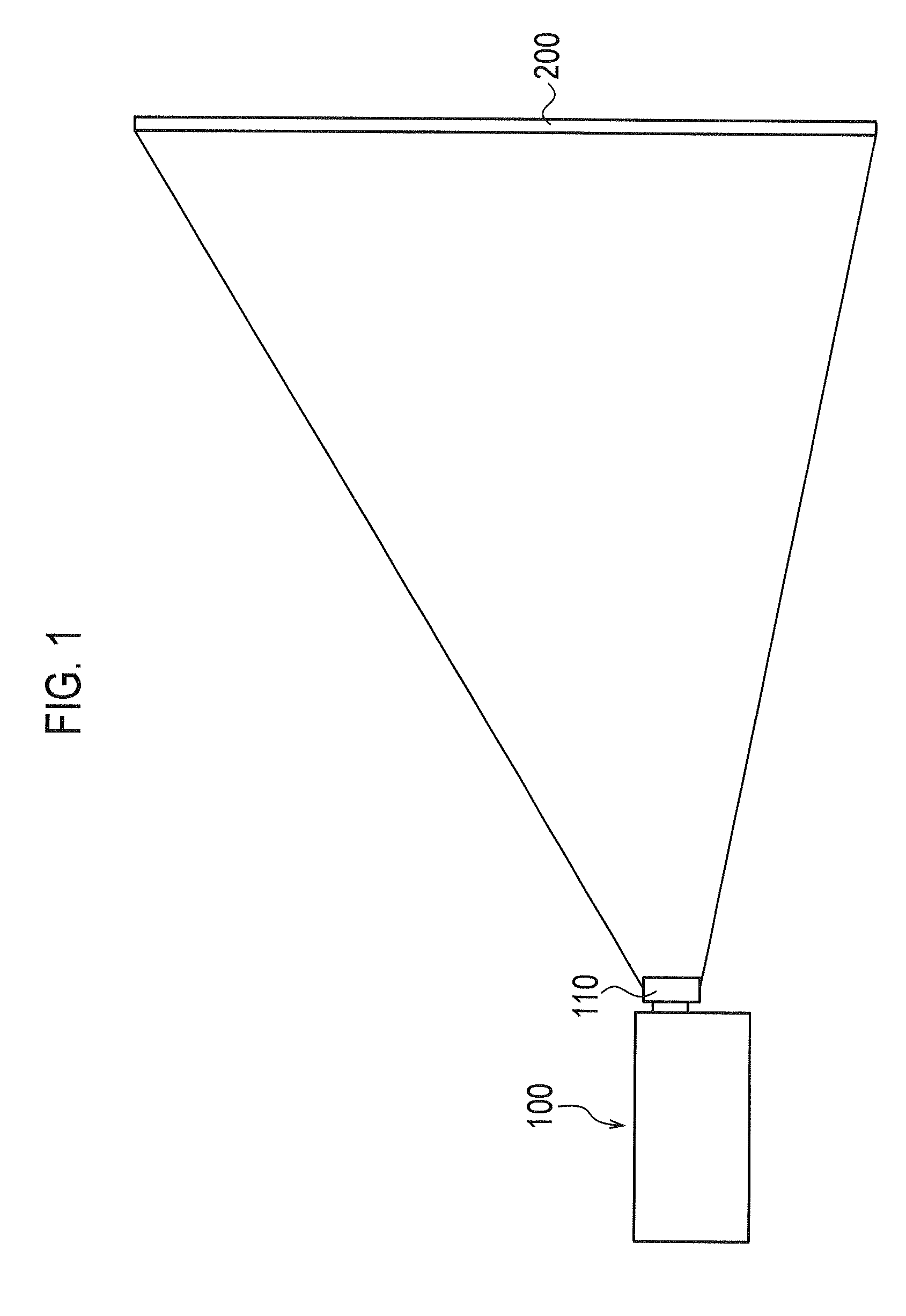
[0036]A summary of a projection image display apparatus of the first embodiment is described below with reference to drawings. FIG. 1 is a schematic diagram of the projection image display device 100 of the first embodiment of the invention.

[0037]As shown in FIG. 1, the projection image display apparatus 100 includes a projection lens unit 110, and projects image light magnified by the projection lens unit 110 on a screen 200. As described later, the projection image display apparatus 100 uses yellow component light as fourth color component light in addition to red component light, green component light and blue component light.

(Schematic Configuration of Lighting Unit)

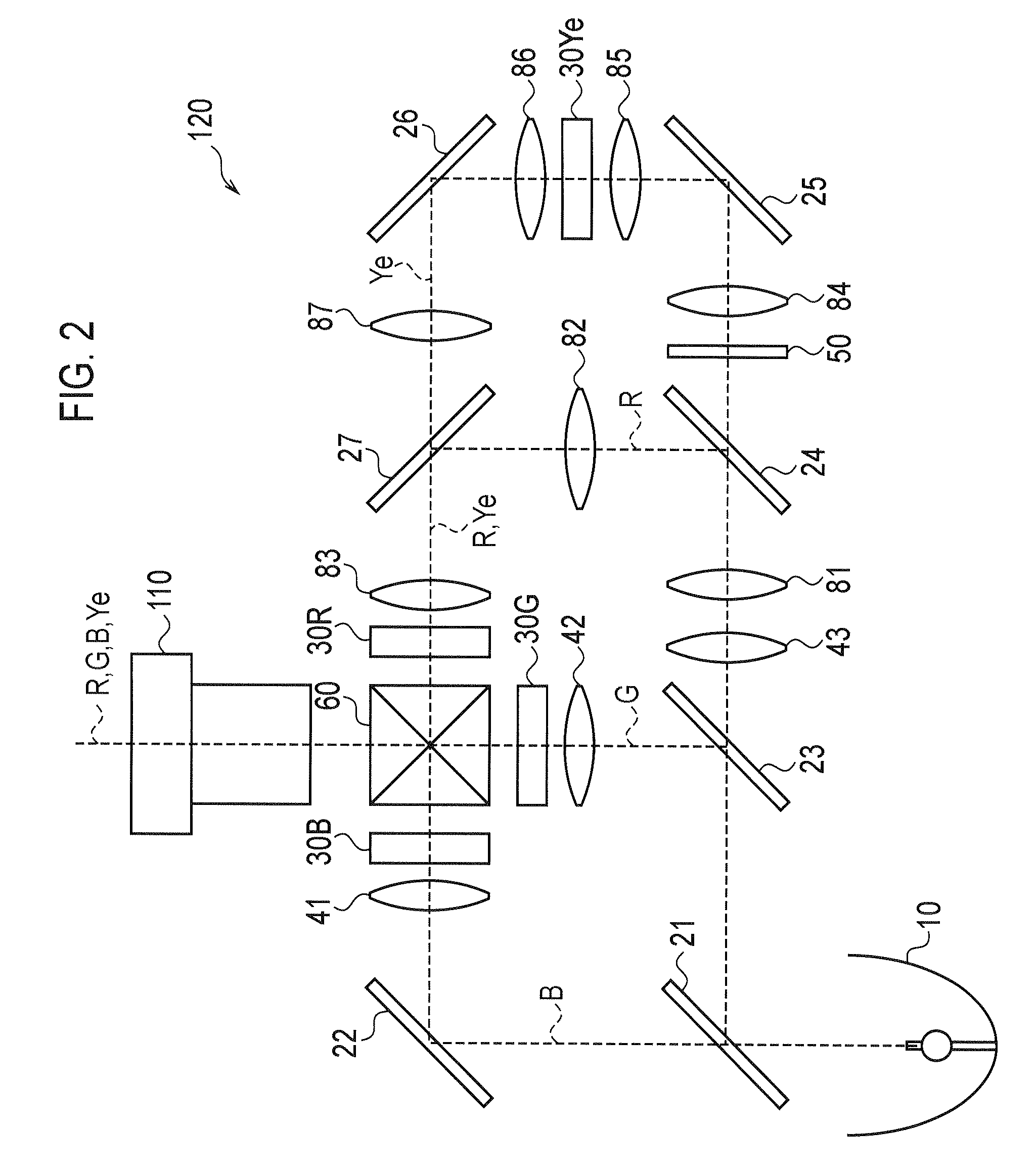
[0038]A schematic configuration of a lighting unit of the first embodiment is described below with reference to the drawings. FIG. 2 is a view showing a schematic configuration of the lighting unit 120 of the first embodiment. It should be noted that in FIG...

second embodiment

[0107]A second embodiment is described below with reference to drawings. Differences between the first embodiment described below and the second embodiment are mainly described below.

[0108]Specifically, in the above described first embodiment, the projection image display apparatus 100 outputs the blue input signal Bin directly to the liquid crystal panel 30B as the blue output signal Bout. In contrast, in the second embodiment, the visibilities of red component light, green component light, blue component light, and yellow component light are taken into consideration, and the projection image display apparatus 100 adjusts the red output signal Rout, a green output signal Gout, a blue output signal Bout, and a yellow output signal Yeout.

(Functions of the Projection Image Display Apparatus)

[0109]Functions of the projection image display device 100 of the second embodiment are described below by referring to drawings. FIG. 7 is a block diagram showing the functions of the projection i...

third embodiment

[0160]A third embodiment is described below with reference to drawings. Differences between the first embodiment and the third embodiment are mainly described below.

[0161]More specifically, in the above-described first embodiment, a superimposition amount of the yellow component light (Ye substitution signal W) is determined from an input signal having a lower intensity between the red input signal Rin and the green input signal Gin.

[0162]In contrast, in the third embodiment, a superimposition amount of yellow component light (Ye substitution signal W) is determined from a mean value of luminance of respective pixels included in a target region and a mean value of saturation thereof.

(Function of the Projection Image Display Apparatus)

[0163]A function of a projection image display apparatus 100 of the third embodiment is described below with reference to the drawings. FIG. 15 is a view for explaining the functions of the projection image display apparatus 100 (controlling unit 130) o...


PUM


Abstract

The image signal converting apparatus is used in a lighting unit. The lighting unit includes a liquid crystal panel modulating a red component light according to a red image signal, a liquid crystal panel modulating a green component light according to a green image signal, and a liquid crystal panel modulating a blue component light according to a blue image signal. Yellow component light is superimposed on any of the red component light, the green component light and the blue component light. The image signal converting apparatus includes a controlling unit which controls a superimposition amount of yellow component light based on a specific image signal among a red image signal, a green image signal, and a blue image signal. A color corresponding to the specific image signal has a hue adjacent to a hue corresponding to the yellow component light. The controlling unit controls a reduction amount of the specific image signal based on the superimposition amount.

Description

CROSS REFERENCE TO RELATED APPLICATION[0001]This application is based upon and claims the benefit of priority from Japanese Patent Application No. 2007-258087, filed on Oct. 1, 2007; the entire contents of which are incorporated herein by reference.BACKGROUND OF THE INVENTION[0002]1. Field of the Invention[0003]The present invention relates to an image signal converting apparatus and an image display apparatus using fourth color component light in addition to red component light, green component light and blue component light.[0004]2. Description of the Related Art[0005]Three-plate projection image display apparatuses have heretofore been widely known, which include a red liquid crystal panel modulating a red component light, a green liquid crystal panel modulating a green component light and a blue liquid crystal panel modulating a blue component light.[0006]To increase luminance and to reduce power consumption, proposed is a projection image display apparatus which uses fourth col...

Claims


Application Information

Patent Timeline
Patent Type & Authority Applications(United States)
IPC IPC(8): G09G5/02
CPCH04N9/3158H04N9/3197H04N9/3182
Inventor INOUE, MASUTAKATANASE, SUSUMUABE, TAKAAKI
Owner SANYO ELECTRIC CO LTD
Why Eureka
Try Eureka