Endodontic Instrument

a technology for endodontic instruments and endoscopy, which is applied in the field of endodontic instruments, can solve the problems of undesirable attachment of clips to shafts b>14/b>, impair the angle of file insertion into the root canal, and impair so as to improve the dexterity of file manipulation, improve the tactile feedback, and improve the effect of visibility

a technology for endodontic instruments and endoscopy, which is applied in the field of endodontic instruments, can solve the problems of undesirable attachment of clips to shafts b>14/b>, impair the angle of file insertion into the root canal, and impair so as to improve the dexterity of file manipulation, improve the tactile feedback, and improve the effect of visibility

US20090181341A1Inactive Publication Date: 2009-07-16LAMPERT CHRIS J

Image

  • Endodontic Instrument
  • Endodontic Instrument
  • Endodontic Instrument

Examples


Embodiment Construction

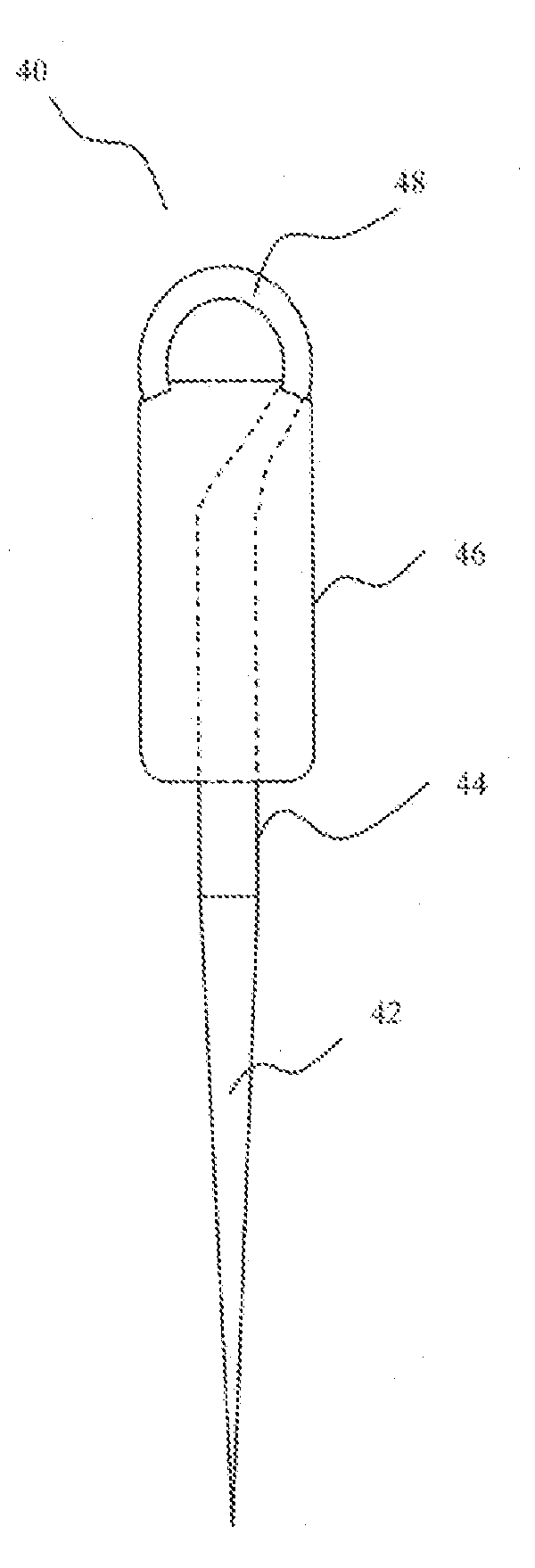
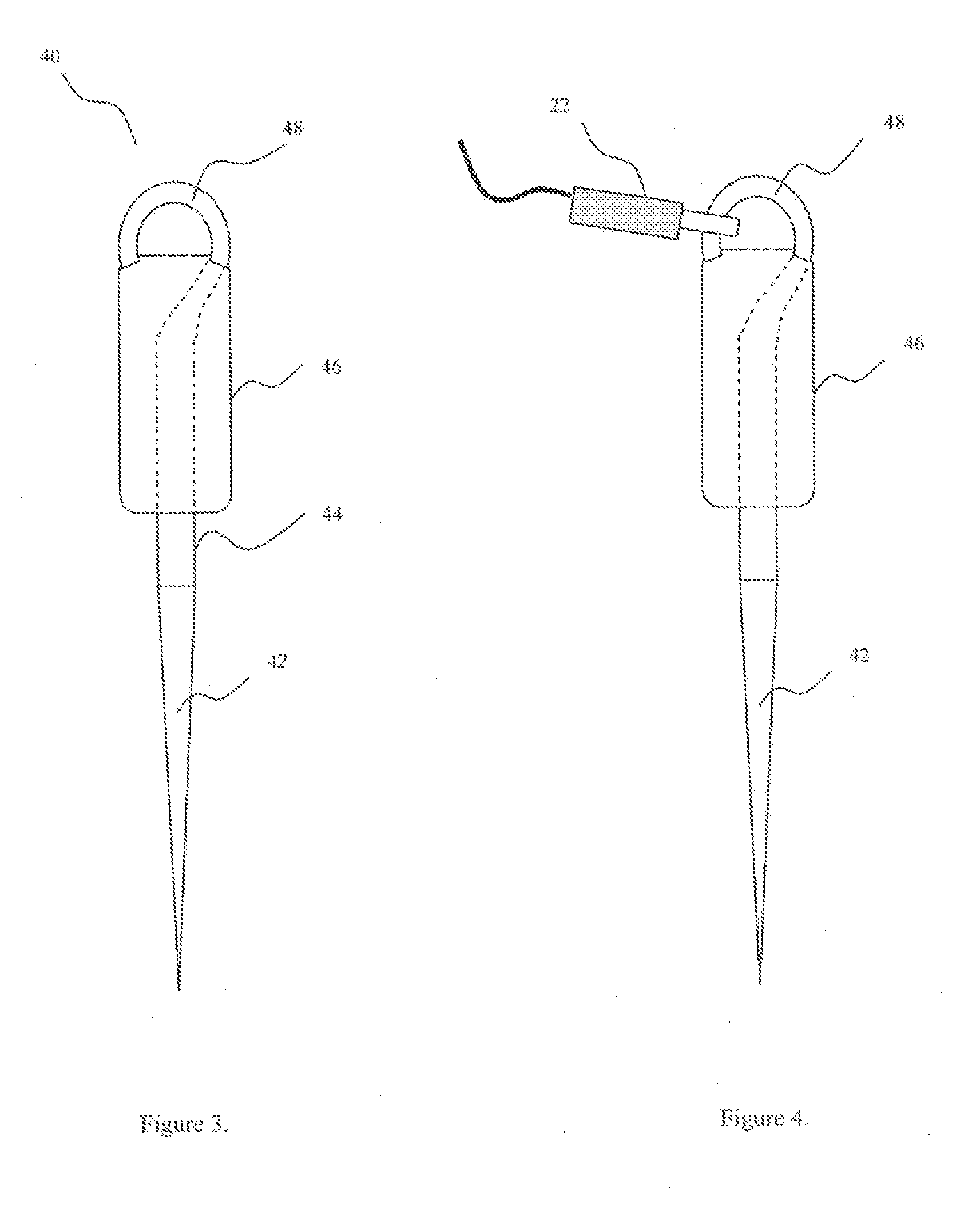
[0021]The inventive endodontic file 40 is shown in FIG. 3 having a connection site 48 for an electronic apex locator wherein the connection site is located on the proximal end of the file handle and has a radius or curved shape which allows the electronic apex locator to be connected at any angle along the radius. Endodontic file 40 is shown as an elongate element having tapered cutting flutes 42 comprising a working end for insertion into a root canal (not shown) and a shaft 44 secured to a handle 46 to be grasped by a user. Handle 46 is secured by any convenient means to shaft 44, for example handle 46 may be an injection molded plastic handle which is molded around shaft 44. Shaft 44 extends in a continuous fashion through handle 46 and out the proximal end of handle 46 and forms a curved radius 48.

[0022]As shown in FIG. 4 the curved radius connection site 48 allows for an electronic apex locator 22 to be connected at any desirable angle along the curved radius. FIGS. 5, 6, 7, an...


PUM


Abstract

An endodontic instrument for root canal treatment is provided having a working portion manipulated by a handle and a curved radiused connection site for the attachment of an electronic apex locator. The curved radiused connection site is located at the proximal end of the file handle and allows the electronic apex locator to be connected to the endodontic instrument at any desirable angle.

Description

[0001]This application claims the benefit of and priority to U.S. Provisional Application No. 61 / 010,949, entitled ā€œEndodontic Instrumentā€, filed Jan. 14, 2008, the entire disclosure of which is hereby incorporated by reference as if set forth in their entirety for all purposes.FIELD OF THE INVENTION[0002]This invention relates generally to endodontic instruments for performing root canal procedures and, more particularly, to a connection assembly for electrically connecting an endodontic file to an electronic apex locator.BACKGROUND OF THE INVENTION[0003]Traditional endodontic files consist of a tapered cutting flute portion having a shaft connected to a handle that is gripped by a user such as, for example, a dentist or an endodontist. Endodontic files have cutting flutes on the working portion and are used to remove the contents of a root canal and to prepare and / or shape the root canal prior to filling it. Endodontic files are also used to determine the length of the root canal ...

Claims


Application Information

Patent Timeline
16 Jul 2009
Publication
US20090181341A1
IPC
A61C5/02
CPC
A61C5/02; A61C19/042; A61C19/041; A61C5/40
Inventors
LAMPERT, CHRIS J.